Megohm Bridge Method:
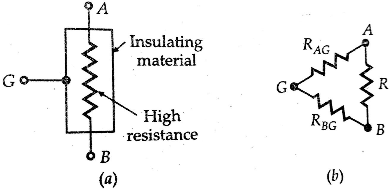
We have seen many methods to find low and medium resistances but now let us discuss methods for high resistance measurement. So now I will explain Megohm bridge method. The below figure(a) shows a very high resistance R with its two main terminals A and B, and a guard terminal, which is put on the insulation. This high resistance may be diagrammatically represented as in figure(b). The resistance R is between main terminals A and B and the leakage resistances RAG and RBG between the main terminals A and B of from a “Three-terminal resistance”.
Must Read:
- Measurement of earth resistance | Fall of potential method | Earth tester
- Measurement of high resistance using direct deflection method
- Measurement of high resistance by Loss of charge method
Let us consider the hypothetical case of a 100 MΩ resistance. We assume that each of the leakage resistances is 100 MΩ, i.e., RAG = RBG =100 MΩ. Let this resistance be measured by an ordinary Wheatstone bridge as shown in the figure(a) below. It is clear that the Wheatstone bridge will measure a resistance of![]() instead of 100 MΩ thus giving an error of 33 percent.
instead of 100 MΩ thus giving an error of 33 percent.
Megohm Bridge Circuit:
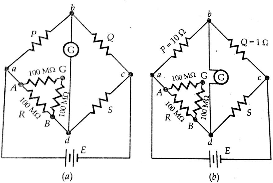
However if the same resistance is measured by a modified Wheatstone bridge as shown in the figure(b) above with the guard connection G connected as indicated, the error in measurement is considerably reduced. For the arrangement shown in figure(b) above resistance, RBG is put in parallel with the galvanometer and thus it has no effect on the balance and only effects the sensitivity of the galvanometer slightly.
The resistance RAG =100 MΩ is put in parallel with a resistance P =100 kΩ and therefore for the arrangement shown the measured value has an error of only 0.01 percent and this error is entirely negligible for measurements of this type.
The arrangement of the below figure illustrates the operation of a Megohm bridge.The below figure shows the circuit of a completely self-contained Megohm bridge which includes power supplies, bridge a members, amplifiers, and indicating instrument.It has a range from 0.1 MΩ to 10⁶ MΩ. The accuracy is within 3% for the lower part of the range to possible 10% above 10,000 MΩ.
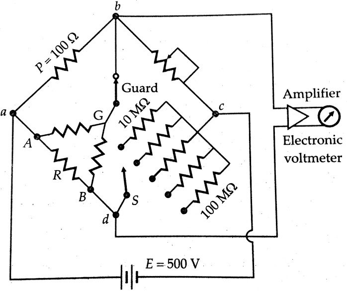
Sensitivity for balancing against high resistance is obtained by use of adjustable high voltage supplies of 500 V or 1000 V and the use of a sensitive null indicating arrangement such as a high gain amplifier with an electronic voltmeter or a CRO.The dial on Q is calibrated 1 – 10 – 100 – 1000 MΩ, with main decade 1 – 10 occupying the greater part of the dial space.
Since unknown resistance R= P.S/Q the arm Q is made, tapered, so that the dial calibration is approximately logarithmic in the main decade, 1 – 10. Arm S gives five multipliers, 0.1, 1, 10, 100 and 1000.The junction of ratio arms P and Q is brought on the main panel and is designated as ‘Guard’ terminal.
Conclusion:
In this, you have learnt Measurement of high resistance by Mega Ohm bridge method.
Comment below for any Queries.