Direct deflection method for measuring high resistance:
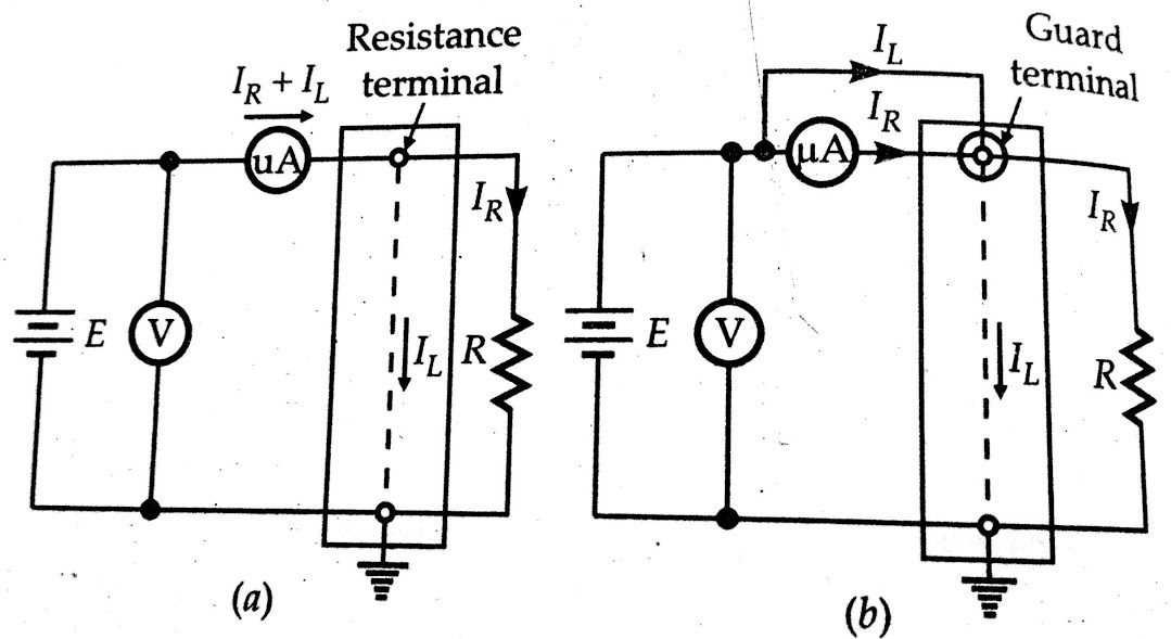
The direct deflection method is that of the figure-(b) above. For high resistance, such as insulation resistance of cables, a sensitive galvanometer of d’Arsonval type (usually having a current sensitivity of at 1000 mm/μA at a scale distance of 1 metre) is used in place of the microammeter. In fact, many sensitive types of galvanometers can detect currents from 0.1 – 1 nA. Therefore, with an applied voltage of 1 kV, resistances as high as 10^12 to 10*10^12 can be measured.
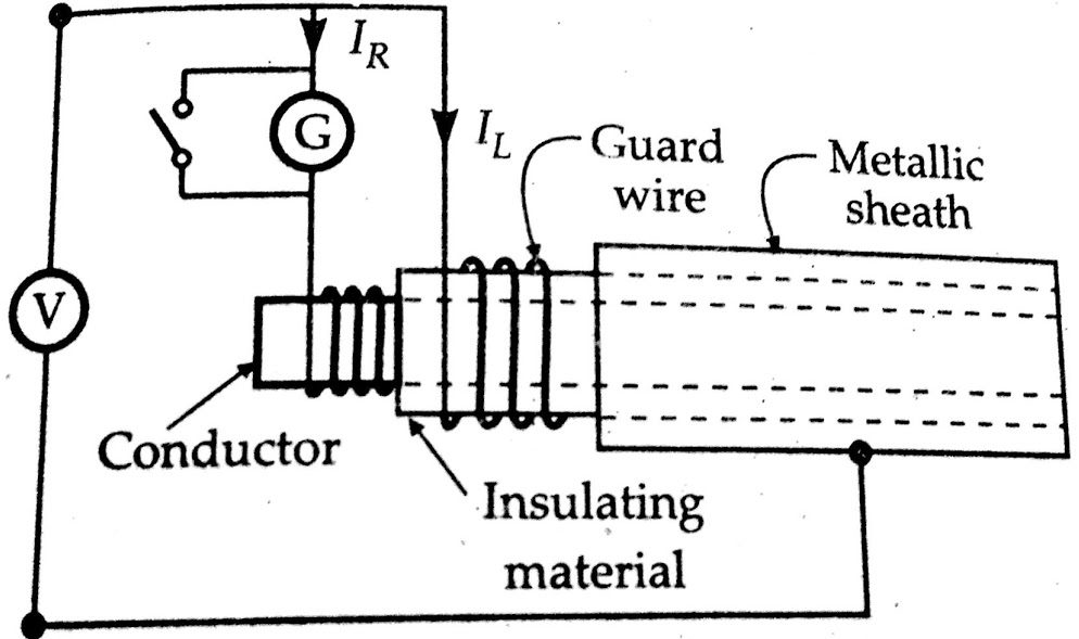
An illustration of the direct deflection method used for measuring the insulation resistance of a cable is shown in the figure below. The galvanometer G measures the current IR between the conductor and the metal Sheath. The leakage current IL, over the insulating material, is carried by the guard wire wound on the insulation and therefore does not flow through the galvanometer.
———————————————————————————————–
If you are an electrical engineering student don’t forget to Read below:
- Method for Measurement of Resistance|Ammeter-Voltmeter Method
- Measurement of high resistance by Loss of charge method
- Measurement of Medium Resistance by Substitution Method
———————————————————————————————–
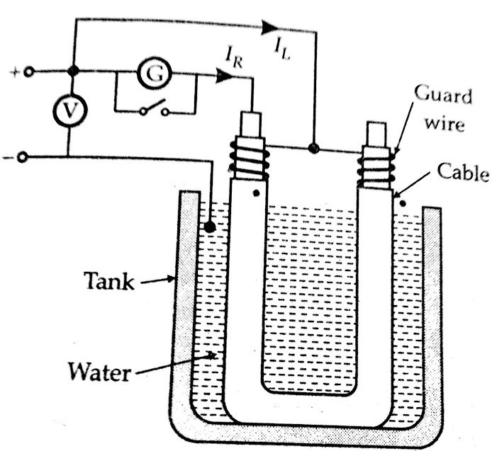
Cables without metal sheaths can be tested in a similar way if cable, except the end or ends on which corrections are made, is immersed in water in a tank. The water and the tank then form the return path for the current. The cable is immersed in slightly saline water for about 24 hours, and the temperature is kept constant (at about 20°C) and then the measurement is taken as in the figure below.
The insulation resistance of the cable R = V / IR .
In some cases, the deflection of the galvanometer is observed, and its scale is afterwards calibrated by replacing the insulation by a standard high resistance (usually 1 MO), the galvanometer shunt being varied, as required to give a deflection of the same order as before.
In tests on cables, the galvanometer should be short-circuited before applying the voltage. The short-circuited connection is removed only after sufficient time has elapsed so that charging and absorption currents cease to flow. The galvanometer should be well shunted during the early stages of measurement, and it is normally desirable to include a protective series resistance (of several MΩ) in the galvanometer circuit.
The value of this resistance should be subtracted from the observed resistance value to determine the true resistance. A high voltage battery of 500 V emf is required and its emf should remain constant throughout the test.
Measurement of volume and surface resistivity:
The direct deflection method is often used for measurement of insulation resistance of insulating material samples available in sheet form. In such cases, we are interested in the measurement of volume resistivity and the surface resistivity of the material.
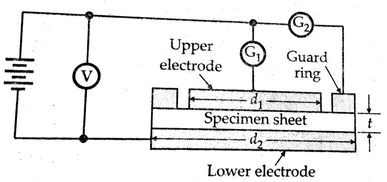
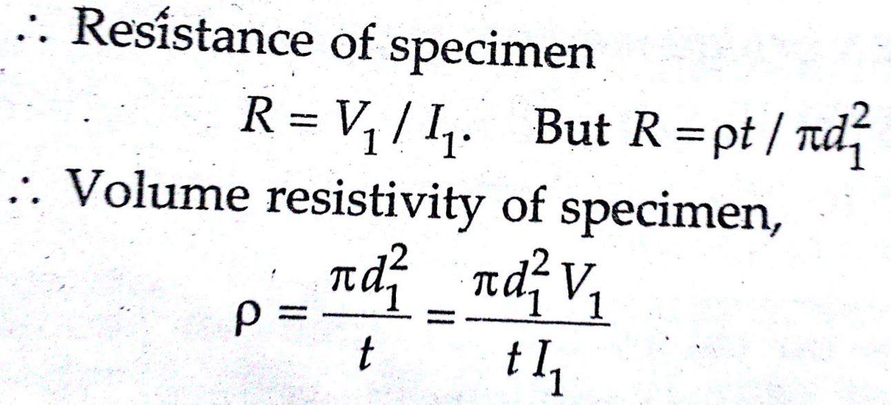
The figure below shows the schematic diagram for measurement of volume and surface resistivities of a specimen of insulating material. The specimen is provided with tin foil or colloidal graphite electrodes; the upper electrode having a guard ring. For measurement of volume resistivity (which in fact is the specific resistance), readings of the voltage applied and the current through the galvanometer are taken. Leakage currents over the edge of the specimen will flow between the guard ring and the lower electrode and hence will not introduce error into the measurement. The volume resistivity, p, can be calculated as follows:
Let d1 = diameter of the upper electrode d1,
r= thickness of the specimen sheet,
V1 = reading of voltmeter,
and I = current through galvanometer G1.
The resistivity of a thin layer of dielectric materials is different from volume resistivity, not only because of an adherent humidity layer but also because of contamination, chemical alterations, absorption of gases, or structural modification.The resistance Rt between two electrodes embedded in or attached to a dielectric medium is composed of volume resistance Rv and surface resistance Rs with (1 / Rt) =(1/ Rv) +(1 /Rs)
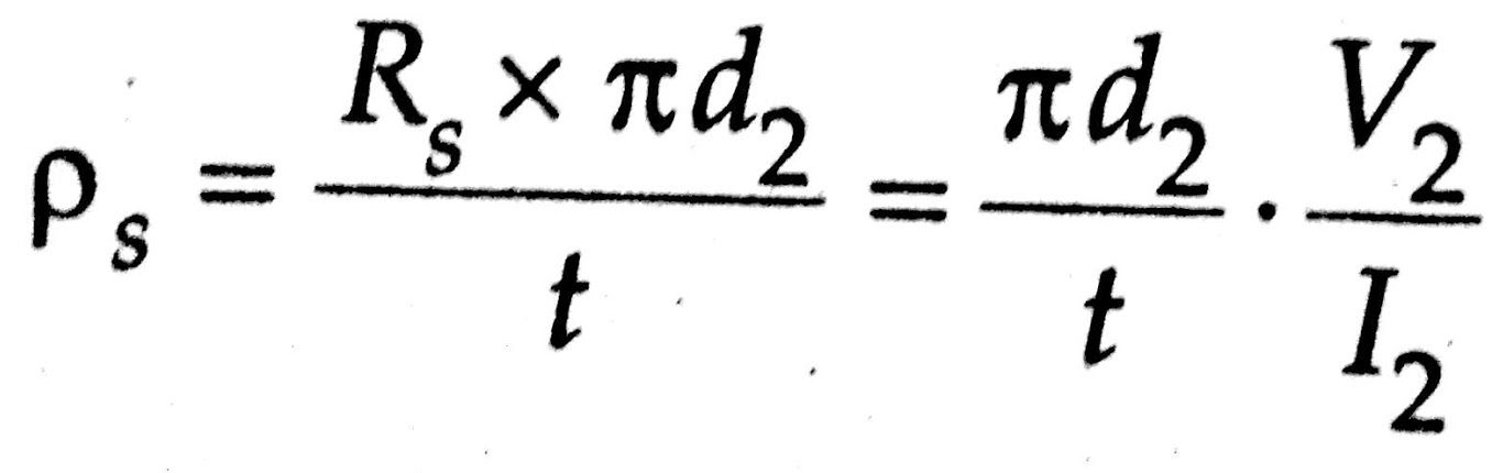
The volume resistance, Rv can be measured separately from surface resistance Rs with the help of guard rings as shown in the figure above. If we want to measure surface resistivity, the galvanometer is placed in position G2. In this position, the galvanometer measures the leakage current, and the current flowing between upper and lower electrodes will be eliminated from the measurement. Let
d2 = diameter of lower electrode disc,
V2 = reading of voltmeter
And I2 = current through galvanometer G2.
Surface resistance, Rs = V2/I2
The leakage current flows along a path of length t and width πd2 and therefore, surface resistivity,
Other forms of specimen and electrodes are also used. For example, the electrodes and guard ring may be mercury, either placed in specially machined recesses, in moulded insulating materials or retained by metal rings on the surface of sheet materials.