Measurement of Earth resistance:
Now here we are going to know the methods for the measurement of earth resistance.
The provision of an earth electrode for an electrical system is necessitated by the following reasons:
1. All the parts of electrical equipment, like casings of machines, switches and circuit breakers, lead sheathing and armouring of cables, tanks of transformers, etc. which have to be at earth potential, must be connected to an earth electrode.The purpose of this is to protect the various parts of the installation, as well as the persons working against damage in case the insulation of a system fails at any point.
By connecting V these parts to an earthed electrode a continuous low resistance path is available for leakage currents to flow to earth. This current operates the protective devices and that the faulty circuit is isolated in case a fault occurs.
2. The earth electrode ensures that in the event of over voltage on the system due to lightning discharges or other system faults, those parts of equipment which are normally dead as far as voltages are concerned, do not attain dangerously high potentials.
3. In a three-phase circuit, the neutral of the system is earned to stabilize the potential of the circuit with respect to earth.
Must Read:
- Measurement of high resistance using direct deflection method
- Measurement of high resistance by Loss of charge method
- Measurement of Medium Resistance by Wheatstone Bridge Method
An earth electrode will only be effective so long it has a low resistance to the earth and can carry large currents without deteriorating. Since the amount of current which an earth electrode will carry is difficult to measure, the resistance value of the earth electrode is taken as sufficiently reliable indication of its effectiveness. The resistance of earth electrode should be low to give good protection and it must be measured.
The main factors on which the resistance of earth system depends are:
1. Shape and material of earth electrode or electrodes used.
2. Depth in the soil at which the electrodes are hurried.
3.The specific resistance of soil surrounding and in the neighbourhood of electrodes.
The specific resistance of the soil is not constant but varies with one type of soil to another. The amount of moisture present in the soil affects its specific resistance and hence the resistance of earth electrode is not a constant factor but suffers seasonal variations.This calls for periodic testing to ensure that the earthing system remains reasonably effective.
The specific resistance of soils varies between wide limits and is very much dependent upon its moisture content.Approximate figures for specific resistance of soil are 80 x 10^3 Ωm in for moist clay to 80 x 10^6 Ωm for sand of normal moisture content.A decrease of the moisture content of 30% is capable of producing an increase of 300% to 400% in specific resistance.Thus it is necessary to make regular checks for earth resistance during the year round.
Methods of Measuring Earth Resistance:
1.Fall of potential method:
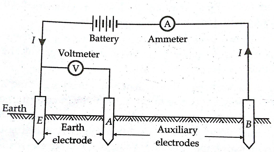
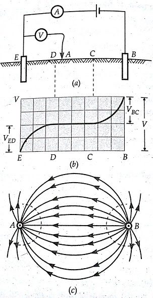
The figure above shows the circuit for measurement of earth resistance with fall of potential method.A current is passed through earth electrode an auxiliary electrode B (which is usually an iron spike) inserted in the earth at a distance away from the earth electrode.A second auxiliary electrode A is inserted in the earth between E and B.The potential difference V between E and A is measured for a given current I.The flow of ground currents is shown in the figure below.
The lines of the first electrode current diverge and those of the second electrode current converge.As a result, the current density is much greater in the vicinity of the electrodes than at a distance from them.The potential distribution between the electrodes is shown in the figure-(b) shown below.It is apparent from this curve that the potential rises in the proximity of electrodes E and B and are constant along the middle section.The resistance of earth, therefore, is
RE =V / I or VEA / I
The position of electrodes E and B is fixed and the position of electrode A is changed and resistance measurements are done for various positions of electrode A.
A graph is plotted between earth resistance against the distance between electrode E and A.This graph is shown in the figure below.
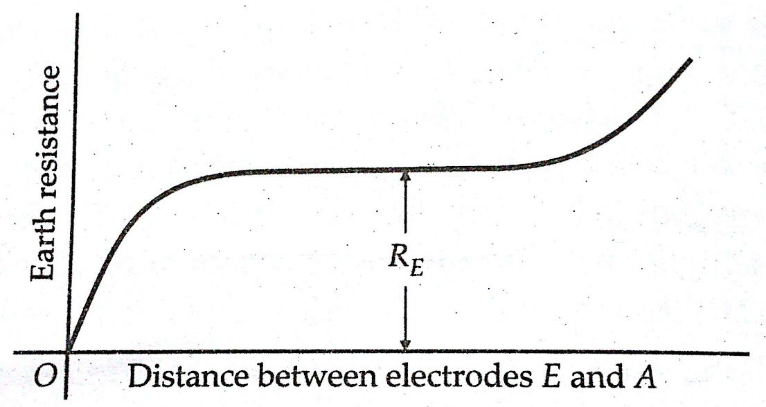
From the above figure of variation of earth resistance with the distance between electrode E and A, it is clear that the measurement of earth resistance depends upon the position of the auxiliary electrode A The earth resistance rises rapidly initially. When the distance between earth electrode E and auxiliary electrode A is increased, it then becomes constant, and when the auxiliary electrode A approaches the auxiliary electrode B, the resistance rises again.
The placing of electrodes is thus very important and serious error may be caused by the incorrect placing of the electrodes.The correct value of resistance of earth, RE, is when the auxiliary electrode A is at such a distance that the resistance lies on the flat part of curve of the figure above.
The spacing between the earth electrode E and the auxiliary electrodes A, B should be large so as to get proper results.The distance may be a few hundred metres in case the earth resistance is low.
2. Earth tester:
The measurement of earth resistance can be measured by an earth tester shown in the figure below. The “Earth Tester” is a special type of Megger and it has some additional constructional features and they are
(i) a rotating current reverser
(ii) a rectifier
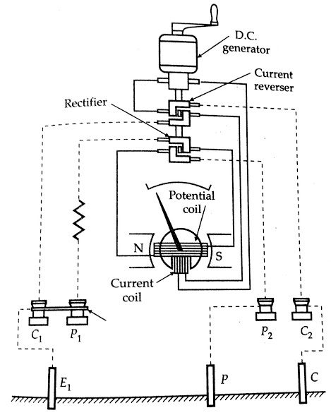
Both these additional features consist of simple commutators made up of ‘L’ shaped segments.They are mounted on the shaft of the hand driven generator.Each commutator has four fixed brushes.One pair of each set of brushes is so positioned that they make contact alternately with one segment and then with the other as the commutator rotates.The second pair of each of set of brushes is positioned on the commutator so that continuous contact is made with one segment whatever the position of the commutator.
The earth tester has four terminals P1 , P2.Two terminals P1 and C1 are shorted to form a common point to be connected to the earth electrode. The other two terminals P2 and C2 are connected to auxiliary electrodes P and C respectively.
The indication of the earth tester depends upon the ratio of the voltage across the pressure coil and the current through the coil. The deflection of its pointer indicates the earth resistance directly. Although the “Earth Tester”, which is a permanent magnet moving coil instrument and can operate on dc only, yet by including the reverser and the rectifying device it is possible to make measurements with ac flowing in the soil.
The sending of ac current through the soil has many advantages and therefore this system is used.The use of ac passing through the soil eliminates unwanted effects due to production of a back emf in the soil on account of electrolytic action.Also, the instrument is free from effects of alternating or direct currents presents in the soil.In the above two ways measurement of earth resistance is done as it is necessary for some particular calculations.
Conclusion:
You have learnt Methods of Measurement of Earth Resistance.
Comment below for any Queries.