Transfer Function & Mathematical Model of Hydraulic System:
The Hydraulic system of interest to control engineers may be classified into,
1.Liquid Level system
2.Hydraulic devices
The liquid level system consists of storage tanks and connecting pipes.The variables to be controlled are liquid height in tanks and flow rate in pipes.The driving force is the relative difference of the liquid heights in the tanks.The Hydraulic devices are devices using incompressible oil as their working medium.In this we will be learning transfer function of hydraulic system.
These devices are used for controlling the forces and motions.The driving force is the high pressure oil supplied by the Hydraulic pumps.Liquids are slightly compressible at high pressures.
In hydraulic system, the compressibility effects may be neglected and conservation of volume is used as the basic physical law. The variables of hydraulic system are volumetric flow rate, q and pressure, R The volumetric flow rate, q is through variable and it is analogous to current. The pressure, P is across variable and it is analogous to voltage.
Three basic elements of hydraulic systems are the Resistance, Capacitance and lnertance.The liquid flowing out of a tank can meet the resistance in several ways.Liquid while flowing through a pipe meet with resistance due to the friction between pipe walls and liquid. Presence of valves, bends, coupling of pipe of different diameter also offer resistance to liquid flow.
Must Read:
The capacitance is an energy storage element and it represents storage in gravity field.The inertance represents fluid inertia and is derived from the inertia forces required to accelerate the fluid in a pipe. It is also an energy storage element.But the energy storage due to inertance element is negligible compared to that of capacitance element.
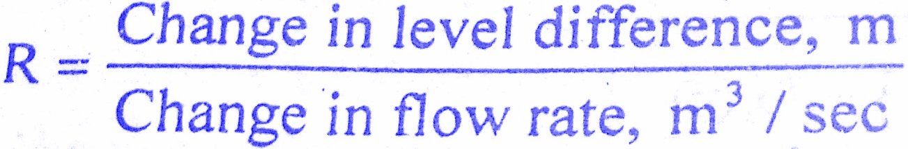
Consider the flow through a short pipe connecting two tanks. The Resistance, R for liquid flow in such a pipe or restriction, is defined as the change in the level difference, necessary to cause a unit change in the flow rate.
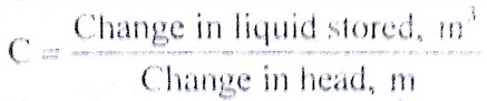
The Capacitance, C of a tank is defined to he the change in quantity of stored liquid necessary to cause in the potential (head).
Example of Liquid Level System:
A simple liquid level system is shown in the below figure with steady flow rate, Q and steady state head,H.
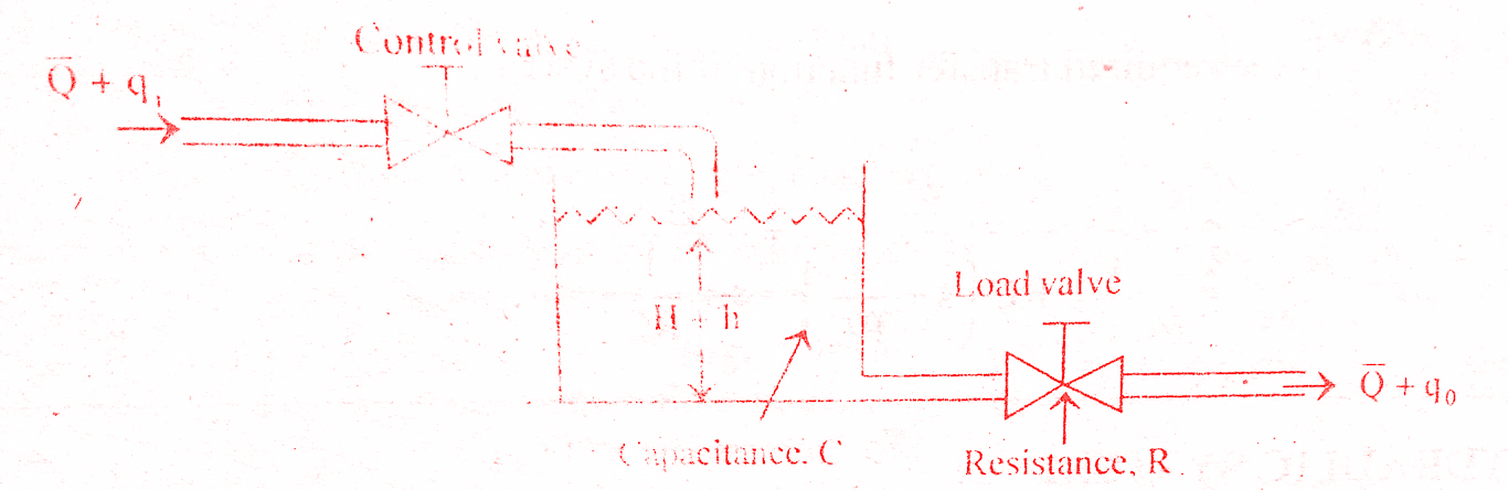
Let Q = Steady state flow rate( before any change has occured)
qi = Small deviation of inflow rate from its steady-state value
qo = Small deviation of outflow rate from its steady-state value
H = Steady state head (before any change has occured)
h = Small deviation of head from its steady state value
Let the system be considered linear.The differential equation governing the system is obtained by equating the change in flow rate to the amount stored in the tank.In a small time interval dt, let the change in flow rate be (qi – qo) and the change in height be dh.
Now, Change In storage = Change in flow rate
C dh = (qi – qo) dh
![]()
qo = h/R
On substituting for qo , we get ,
![]()
RC dh/dt + h = qi R
The above equation is the differential equation governing the system.The term RC is the time constant of the system .On the Laplace’s transform of above equation we get,
![]()
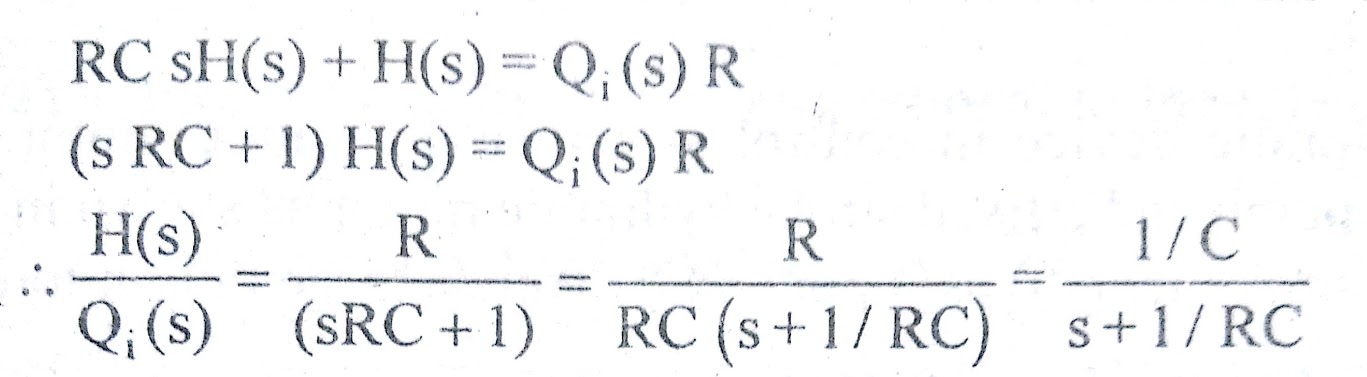
The above equation is the required transfer function of the Hydraulic system.
Must Read:
Hydraulic Devices:
The hydraulic devices are used in hydraulic feedback systems and in combined electro-mechanical-hydraulic systems. in hydraulic devices, power is transmitted through the action of fluid flow under pressure and the fluid is incompressible.
The fluid used are petroleum based oils or non-inflammable synthetic oils. The hydraulic devices used in control systems are generally classified as hydraulic motors and hydraulic linear actuators.The output of hydraulic motor is rotary motion and that of linear actuator is translational.
The hydraulic motor is physically smaller in size than an electric motor for the same power output.Also, the hydraulic components are more rugged than the corresponding electrical components.The applications of hydraulic devices are power steering and brakes in automobiles, the steering Mechanism of large ships, the control of large machine tools, etc.
Advantages of Hydraulic System:
(i) Hydraulic fluid acts as a lubricant and coolant
(ii) Comparatively small sized hydraulic actuators can develop are forces or torques
(iii)Hydraulic actuators can be operated under continuous, intermittent, reversing, and ,called conditions without damage
(iv)Hydraulic actuators have a higher speed of response.They offer fast starts, stops and speed reversals
(v) With availability of both linear and rotary actuators, the design has become more flexible
(vi) Because of low leakages in hydraulic actuators,when loads are applied the drop in speed will be small.
(vii) For the same power output, hydraulic system is much smaller in physical size than an electric motor.
(viii) Hydraulic components are rapidly acting and more rugged compared to the corresponding electrical component.
Disadvantages of Hydraulic Devices:
(i) Hydraulic power is not readily available compared to electric power.
(ii)They have the inherent problems of leaks and of sealing them against foreign particles
(iii) Operating noise
(iv) Costs more when compared to electrical system
(v) Tendency to become sluggish at low temperature because of increasing viscosity of fluid
(vi)Fire and explosion hazards exist
(vii) Hydraulic devices are not flexible as electric cables
(viii)Because of the non-linear and other complex characteristics involved, it is difficult to design sophisticated hydraulic systems.
Transfer function of Hydraulic System:
The most frequently used hydraulic device in control system is hydraulic motor-pump set.It consists of a variable stroke hydraulic pump and a fixed stroke hydraulic motor as shown in the below figure.The device accepts a linear displacement (stroke length) input and delivers a large output torque.Let us now derive the transfer function of hydraulic system.
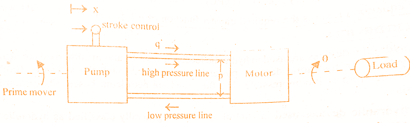
The hydraulic motor is controlled by the amount of oil delivered by the pump.By mechanically changing the pump stroke, the oil delivered by the pump is controlled.Like in a DC generator and dc motor, there is no essential difference between hydraulic pump and motor.In a pump the input is mechanical power and output is hydraulic power and in a motor, it is vice versa.
Let qp = Rate at which the oil flows from the pump
qm = Oil flow rate through the motor
q = Leakage flow rate
qc = compressibility flow rate
x = Input stroke length
θ = Output angular displacement of motor
P = Pressure drop across motor
The rate at which the oil flow from the pump is proportional to stroke angle, i.e., qp ∝ x.
Oil flow rate from-the pump, qp = Kp x
where Kp = Ratio of rate of oil flow to unit stroke angle.
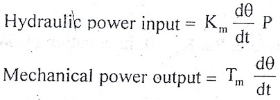
The rate of oil flow through the motor is proportional to motor speed, i.e., qm ∝ dθ/dt.
Must Read:
Oil flow rate through motor, qm = Km dt
where Km = Motor displacement constant.
All the oil from the pump does not flow through the motor in the proper channels. Due to back pressure in the motor, a portion of the ideal flow from the pump leaks back past the pistons of motor and rump. The back pressure is the pressure that is built up by the hydraulic flow to overcome the resistance 😮 free movement offered by load on motor shaft.
It is usually assumed that the leakage flow is proportional to motor pressure, i.e. qi ∝ P
Leakage flow rate, qi = Ki P
where Ki = constant.
The back pressure built up by the motor not only causes leakage flow in the motor and pump but oil in the lines to compress.Volume compressibility flow is essentially proportional to pressure and therefore the rate of flow is proportional to the rate of change of pressure, i.e. qc ∝ dP/dt
Compressibility flow rate, qc = Kc dP/dt
where Kc = Coefficient of compressibility.
The rate at which the oil flows from the pump is given by sum of oil flow rate through the motor, leakage flow rate and compressibility flow rate.
qp = qm + qi + qc
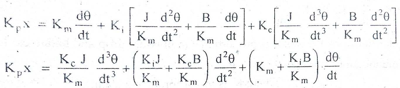
On substituting from above equations,we get
![]()
The torque Tm developed by the motor is proportional to pressure drop and balances load torque.
Hydraulic motor torque, Tm = Kt P
where Kt is motor torque constant.
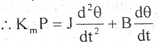
If the load is assumed to consist of moment of inertia J and viscous friction with coefficient B, then,
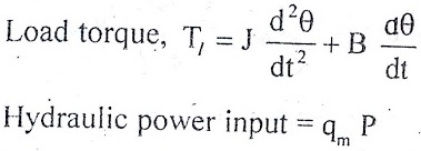
On substituting for qm, we get,
On substituting for Tm, we get,
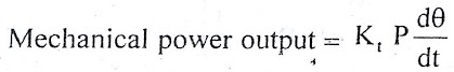
If hydraulic motor losses are neglected or include-d as a part of load, then the hydraulic motor input is equal to mechanical power output of hydraulic motor.
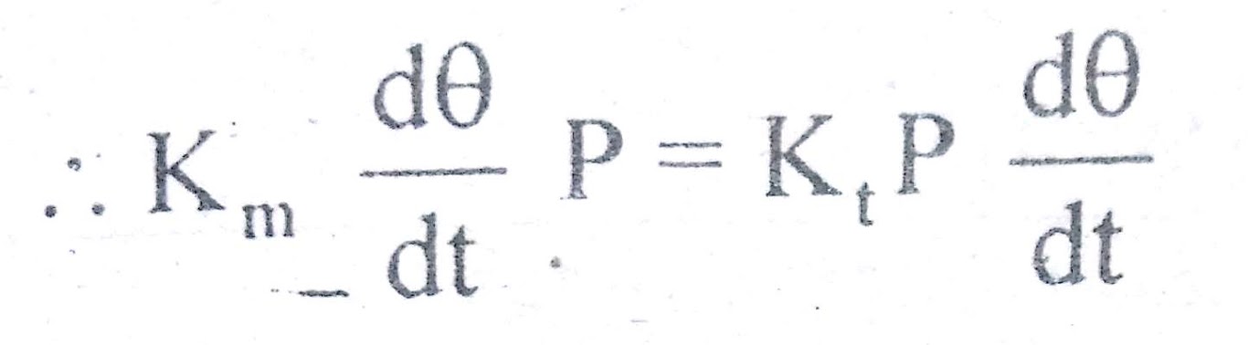
From equation, it is clear that Km = Kt .
Hence we can write,
Tm = Kt P = Km P
Since the motor torque equals load torque, Tm = Tl
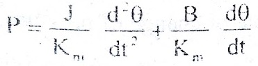
On differentiating above equation w.r.t ,we get,
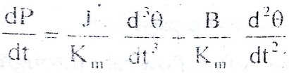
On substituting for P and dP/dt ,we get,
Must Read:
On taking Laplace transform with zero initial conditions , we get,
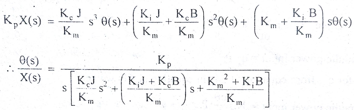
In hydraulic systems,normally Kc << Km , therefore ,Put Kc = 0 in above equation.
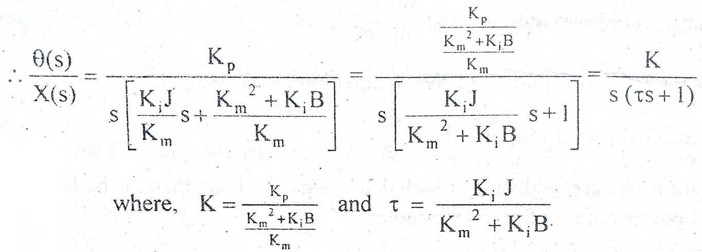
The above equation is the required transfer function of hydraulic system.
Conclusion:
In this post we have learnt Transfer Function & Mathematical Model of Hydraulic System.You can download this article as pdf,ppt.
Comment below if you have any queries!
It really interests me to read such articles, thanks for sharing. Blogs like yours and info really https://tsca.com.ph/ helps me learn more day by day.
Thank you, TSCA for taking the time to comment on my blog. I’m glad that you enjoyed the blog post.
Oh, wow! This article certainly reminds me of my cousin who’s been working hard lately to build a brand new hydraulic pump for his home garage workshop. You got a point there by suggesting that hydraulic fluids could prevent our entire system from experiencing friction and warmth. He should totally refer to a professional regarding this matter so he could end up creating a satisfactory result.
Thank you Amy for reading and commenting!