Current transformers (CTs) are essential components in electrical systems, responsible for transforming high currents to manageable levels for accurate measurement and protection purposes. Ensuring the proper functioning of CTs is vital to maintaining the reliability and safety of power systems.
1)Mutual Inductance Method of Testing:
This is one of the oldest ways of current Transformers testing. This is an absolute method using the null technique. The connections are shown in the below figure.
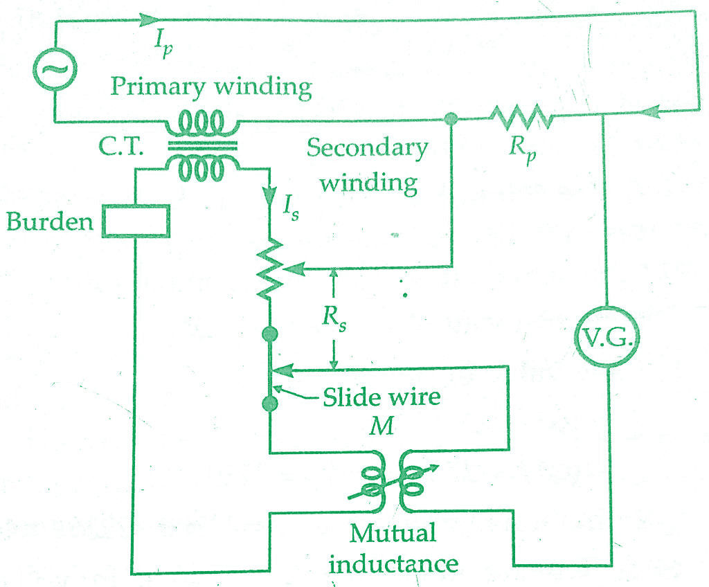
Rp and Rs are low resistance, non-inducts voltage non-conductive shunts, Rs is variable while Rp is fixed. Rs has a slide wire for fine adjustment of resistance.The voltage drop across resistance Rp is matched against voltage drop across Rs.A vibration galvanometer is put in the circuit to indicate the balance conditions.Assuming, for the moment that there is no phase difference between Ip and Is the vibration galvanometer will indicate zero deflection.
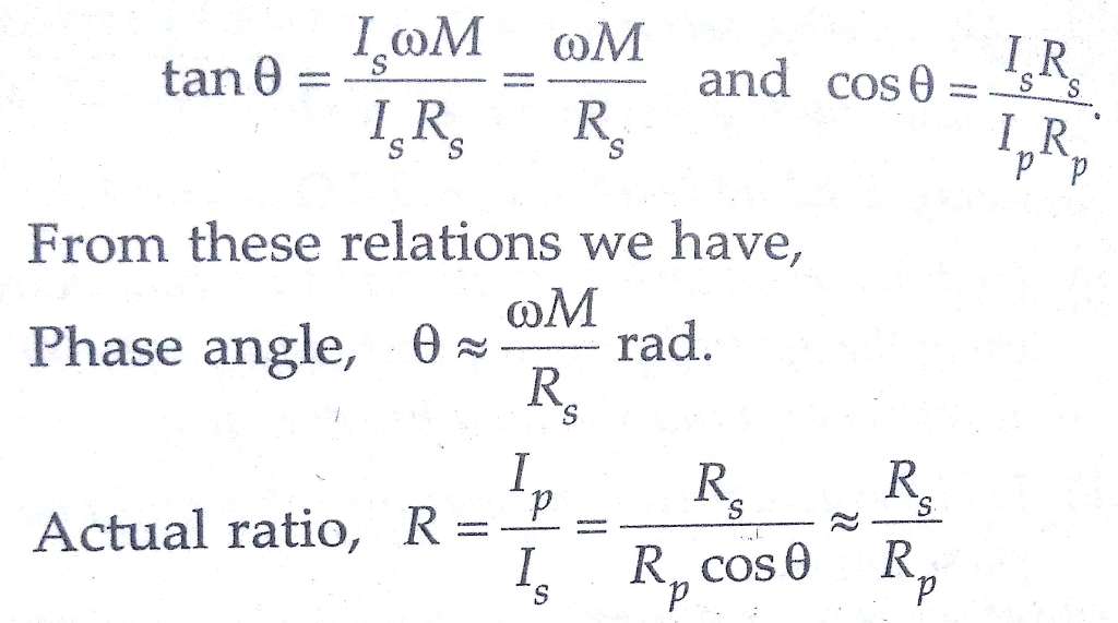
if Ip Rp =Is Rs or Ip /Is =Rs/Rp
Therefore, Rs and Rp should be so chosen that the ratio Rs / Rp is nearly equal to the nominal ratio of the current transformer.Resistance Rs is adjusted to render the two voltage drops equal.In order to obtain zero deflection the magnitude and also the phase of the voltage drops should be same.
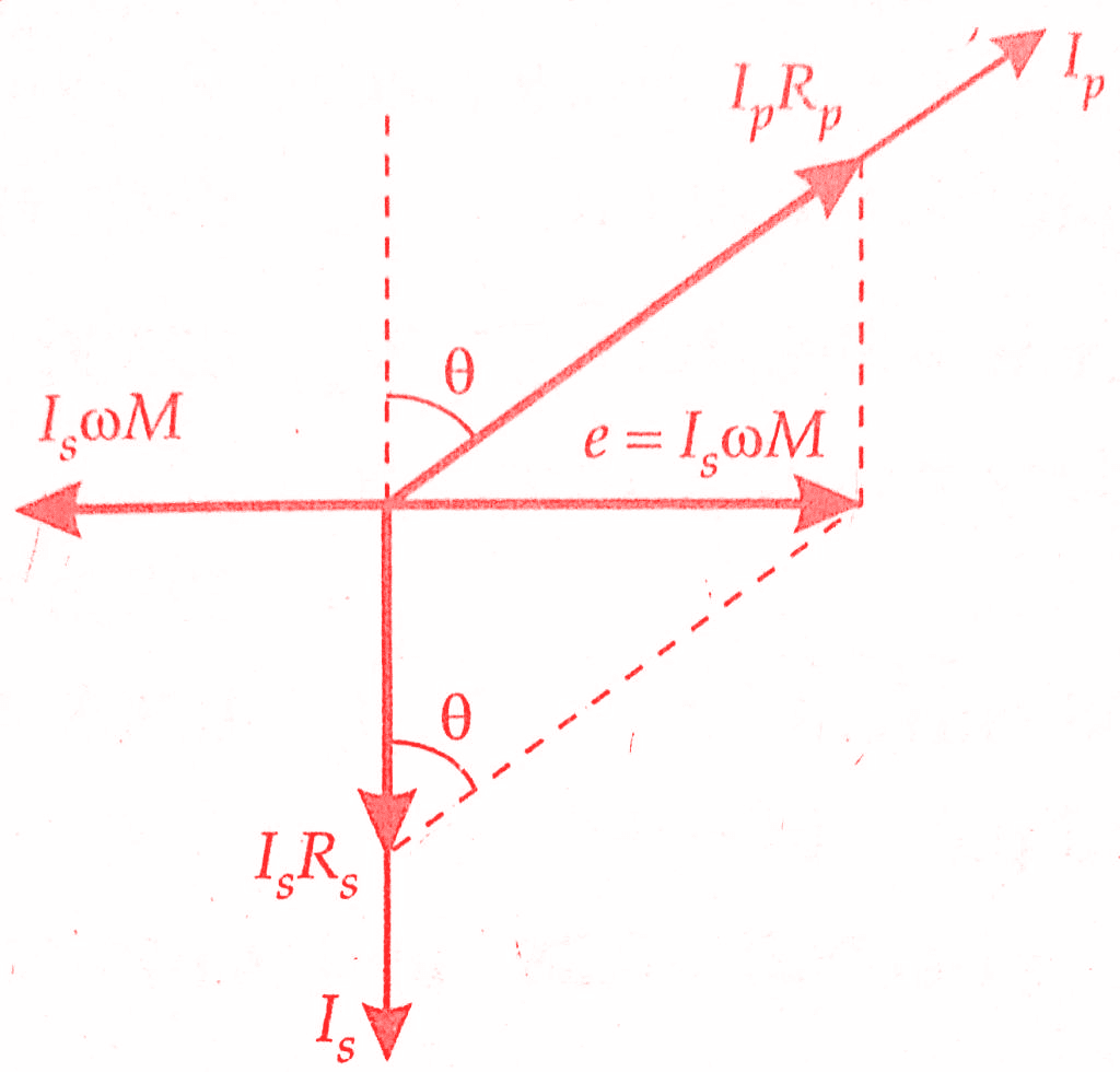
Thus a mutual inductance M is put to compensate for phase difference between Ip and Is as without any phase compensating device it will be impossible to obtain balance with resistance alone. The figure below represents the phasor diagram for mutual inductance method under balance conditions.
It should be noted that the secondary load circuit includes the resistance Rs impedance of primary winding of mutual inductance and also the impedance marked burden. This must be taken into account while stating the burden at which the errors have been measured.
2)Silsbee’s method of Testing:
Silsbee’s method is a classic technique for testing the accuracy of current transformers. Named after its inventor, Francis Marion Silsbee, this method involves injecting a known primary current into the CT’s primary winding and comparing the secondary current produced against the expected value. The primary objective of this testing is to verify whether the CT’s turns ratio and phase angle error are within acceptable limits.
Key Components of Silsbee’s Method:
Primary Current Injection Source: To perform Silsbee’s method, a stable and calibrated current source is required. This source generates a known and controlled primary current that is injected into the CT’s primary winding.
Secondary Current Measurement Equipment: Accurate secondary current measurement devices, such as ammeters, are used to measure the output current of the CT’s secondary winding.
Burden Resistance: A burden resistance is connected across the secondary winding of the CT during testing. This simulates the load that the CT will experience in actual operating conditions.
Phase Angle Meter: A phase angle meter is used to measure the phase difference between the primary current and the secondary current. This phase angle error indicates the accuracy of the CT’s performance.
Testing Procedure:
Preparation: Ensure that the CT is properly connected, and all connections are secure. Set up the primary current injection source, secondary current measurement equipment, burden resistance, and phase angle meter.
Calibration: Calibrate the primary current injection source to generate a known and accurate primary current. This can be done using precision equipment and techniques.
Injection of Primary Current: Inject the calibrated primary current into the CT’s primary winding. Ensure that the primary current is stable and maintained at the desired level.
Measurement of Secondary Current: Measure the secondary current produced by the CT’s secondary winding using accurate ammeters or other appropriate measurement devices.
Calculation of Turn Ratio: Calculate the turn ratio of the CT by dividing the injected primary current by the measured secondary current.
Calculation of Phase Angle Error: Measure the phase angle between the injected primary current and the measured secondary current using the phase angle meter. This angle represents the phase angle error of the CT.
Comparison and Analysis: Compare the calculated turn ratio and phase angle error with the CT’s specified values. If they fall within acceptable limits, the CT is considered accurate and reliable.
Benefits of Silsbee’s Method:
Accurate Performance Verification: Silsbee’s method provides a direct and accurate way to verify the performance of current transformers. It ensures that the CT accurately transforms primary current into secondary current under real-world conditions.
Detection of Abnormalities: This testing method can help identify abnormalities such as winding defects, short circuits, or open circuits within the CT. Such issues can affect the CT’s accuracy and reliability.
Maintenance and Troubleshooting: Regular testing using Silsbee’s method can be an integral part of CT maintenance programs. If deviations from expected values are detected, maintenance personnel can take corrective actions promptly.
System Reliability: Accurate CTs are essential for reliable power system operation. By using Silsbee’s method to ensure their accuracy, utilities can prevent errors in power measurement, protection, and control.
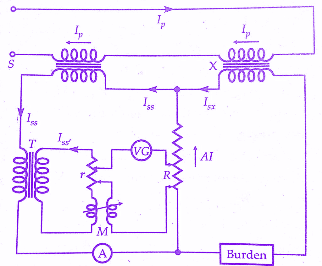
Silsbee’s method is a comparison method used for Current Transformers testing. There are two types of Silsbee’s methods; deflectional and null. Only the deflectional method is described here. The arrangement for this method is shown schematically in below figure. Here the ratio and phase angle of the test transformer X are determined, in terms of that of a standard transformer S having the same nominal ratio.
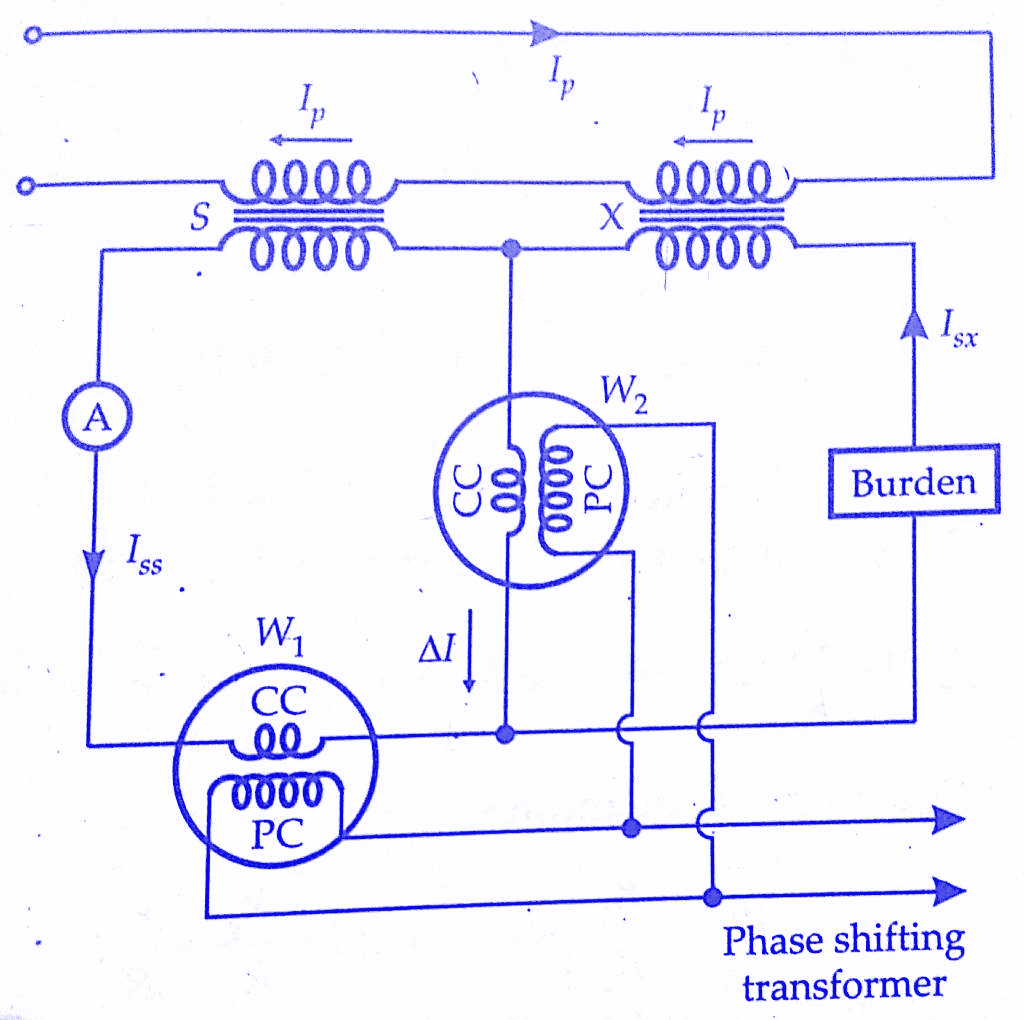
The two transformers are connected with their primaries in series. An adjustable burden is put in the secondary circuit of the transformer under test.An ammeter is included in the secondary circuit of the standard transformer so that the current may be set to the desired value.W1 is a wattmeter whose current coil is connected to carry the secondary current of the standard transformer.
The current coil of wattmeter W2 carries a current ∆I which is the difference between the secondary currents of the standard and test transformers. The voltage circuits of the wattmeters (i.e., their pressure coils) are supplied in parallel from a phase shifting transformer at a constant voltage V. The phasor diagram is shown in the below figure.
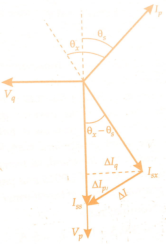
1.The phase of the voltage is so adjusted that wattmeter W1 reads zero. Under these conditions, voltage V is in quadrature with current Iss.The position of voltage phasor for this case is shown as Vq.
Reading of wattmeter, W1,
W1q = Vq Iss cos 90°= 0
Reading. of wattmeter, W2,
W2q = Vq x component of current ∆I in phase with
Vq = VqIq = Vq Isx sin(θx – θs)
where θx = phase angle of current transformer under test,
θs = phase angle of standard current transformers.
2. The phase of voltage V is shifted through 90° so that it occupies a position Vp and is in phase with Iss
Reading of wattmeter W1,
W1p = Vp Iss Cos θ = VpIss
Reading of wattmeter W2,
W2p = Vp x component of current ∆l in phase with Vp
= Vp x ∆Ip = Vp[Iss —Isx Cos(θx — θs)]
If the voltage is kept same for both sets of readings, then
V = Vp – Vq.
We have,
W2q = VIsx Sin(θx –θs), W1p =VIss
= VIss — Isx Cos(θx – θs)
= VIss —VIsx Cos(θx – θs)
≈ W1p —VIsx cos(θx – θs) ≈ W1p – VIsx
as (θx – θs) is very small and, therefore, cos (θx – θs) =1.
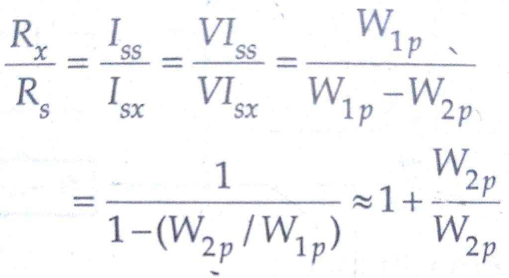
For above, VIsx =W1p — W2p.
Actual ratio of current transformer under test, Rx = Ip / Isx.
Actual ratio of the standard transformer, Rs = Ip /Iss.
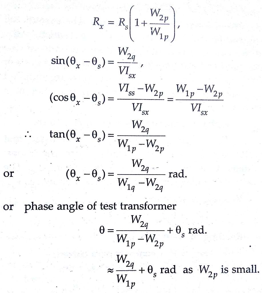
Hence if the ratio and phase angle errors of the standard transformer are known, we can compute the errors of the test transformer.W2 must be a sensitive instrument. Its current coil may be designed for small values. It is normally designed to carry about 0.25 A for testing Current Transformers having a secondary current of 5A.
In conclusion, current transformers play a critical role in power system operation, and their accuracy is paramount. Silsbee’s method offers a comprehensive and effective approach to test CTs, ensuring that they perform as expected under different operating conditions. By understanding the principles, components, and procedure of Silsbee’s method, power system professionals can enhance the reliability and performance of their networks. Regular testing using this method contributes to maintaining accurate measurements, efficient protection, and overall system stability.
3)Arnold’s method of Testing Current Transformer:
Arnold’s method is an advanced technique for testing current transformers that goes beyond traditional testing methods. Named after its creator, E.H. Arnold, this method is based on the principle of transient response analysis. Instead of relying solely on steady-state measurements, Arnold’s method involves injecting a transient signal into the primary winding of the CT and analyzing its response on the secondary side.
Advantages of Arnold’s Method:
- Sensitivity to Internal Faults: Arnold’s method is exceptionally sensitive to internal faults or anomalies within the CT, which might not be detectable using conventional testing methods. It can uncover issues such as turn-to-turn faults, shorted turns, core saturation, and winding deformities.
- Improved Diagnostic Capability: By analyzing the transient response of the CT, Arnold’s method can provide detailed information about the physical and electrical characteristics of the CT, offering a more comprehensive diagnostic capability.
- Non-Intrusive Testing: Unlike some testing methods that require disconnection of the CT from the circuit, Arnold’s method can often be performed without disconnecting the CT, minimizing downtime and service disruptions.
Testing Procedure using Arnold’s Method
- Signal Injection: A transient signal, often a high-frequency pulse or square wave, is injected into the primary winding of the CT.
- Response Analysis: The resulting transient response on the secondary side of the CT is captured and analyzed. The response waveform is then compared to the injected signal to extract valuable information about the CT’s characteristics.
- Data Interpretation: Skilled technicians interpret the acquired data to identify any anomalies or discrepancies in the CT’s performance. Comparing the transient response with reference data helps in assessing the health of the CT.
Significance in Power System Maintenance:
- Early Fault Detection: Arnold’s method allows for the early detection of internal faults or deteriorations in CTs, enabling timely maintenance and preventing potential system failures.
- Enhanced Reliability: By identifying hidden faults, CTs can be replaced or repaired before they compromise the overall reliability of the power system.
- Optimized Performance: Regular testing using Arnold’s method ensures that CTs operate within their specified accuracy limits, resulting in accurate measurements and reliable protection.
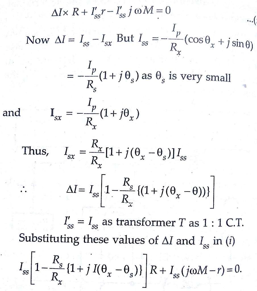
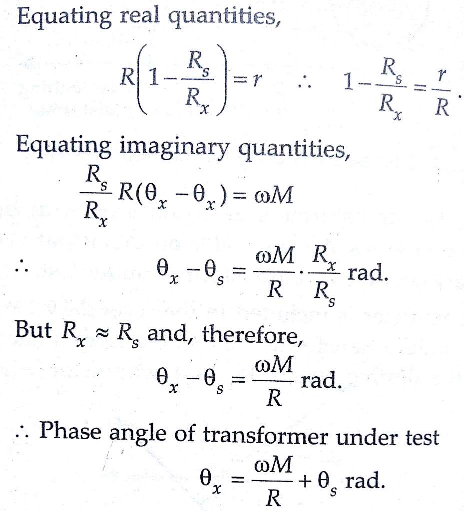
This is a comparison current transformer testing involving null techniques. Arnold’s method is used for getting very accurate results. The errors of the transformer under test X are compared with those of standard transformer. In order to isolate the measuring circuit from the secondaries of CTs, a 5/5 current transformer T is used. This current transformer has negligible errors.
Conclusion:
In the ever-evolving landscape of power systems, the importance of accurate measurement and reliable protection cannot be overstated. Current transformers play a pivotal role in these aspects, making their proper functioning crucial. While traditional testing methods offer valuable insights, Arnold’s method takes CT testing to a new level by revealing intricate details about the CT’s internal state.
With its sensitivity to internal faults, non-intrusive nature, and enhanced diagnostic capability, Arnold’s method empowers power system engineers and technicians to ensure the integrity, safety, and reliability of electrical networks. As technology advances, embracing advanced testing techniques like Arnold’s method becomes essential to stay ahead in the pursuit of a robust and resilient power infrastructure.
Now here we have learnt Current Transformers Testing – Silsbee’s & Arnold’s Method. You can download this article as pdf, ppt.
Comment below for any Queries.
HOW DO WE KNOW IF THE TEST ON THE CURRENT TRANSFORMER IS SUCCESSFUL OR WHETHER IT IS IN A GOOD CONDITION ?
AND CAN YOU GIVE ME A BRIEF EXPLANATION LIKE DEFINITION KIND OF THING FOR THESE THREE METHODS??
Thank you for your comment and for asking about how to determine the success of a test on a current transformer and for a brief explanation of three methods: the Mutual Inductance Method, Silsbee’s Method, and Arnold’s Method.
To determine the success of a test on a current transformer, it is important to compare the results of the test to the manufacturer’s specifications or to established standards. If the results of the test meet or exceed the specifications or standards, then the test can be considered successful. If the results do not meet the specifications or standards, then the transformer may not be in good condition and further testing or repairs may be necessary.
Here is a brief explanation of the three methods you mentioned:
Mutual Inductance Method: This method is used to measure the mutual inductance of a current transformer, which is the inductance that exists between the primary and secondary windings of the transformer. The test involves measuring the voltage that is induced in the secondary winding when a known current is passed through the primary winding. The mutual inductance is then calculated using the formula M = (V * N2) / (I * N1), where M is the mutual inductance, V is the induced voltage in the secondary winding, N1 and N2 are the number of turns in the primary and secondary windings, and I is the primary current.
Silsbee’s Method: This method is used to measure the ratio error and phase angle error of a current transformer. The test involves measuring the primary and secondary currents and voltages of the transformer at various load levels and calculating the ratio error and phase angle error using the formulas: Ratio Error = (I2 / I1) – (V2 / V1) and Phase Angle Error = arctan [(I2 * V1) – (I1 * V2)] / [(I1 * V1) + (I2 * V2)].
Arnold’s Method: This method is used to measure the accuracy of the current ratio and phase angle of a current transformer. The test involves measuring the primary and secondary currents and voltages of the transformer at various load levels and calculating the current ratio and phase angle using the formulas: Current Ratio = I2 / I1 and Phase Angle = arctan [(I2 * V1) – (I1 * V2)] / [(I1 * V1) + (I2 * V2)].
I hope this helps to answer your questions. If you have any further questions or comments, please don’t hesitate to ask.