Testing of Potential Transformers:
1)Absolute null method of Testing Potential Transformers :
The figure below shows the connections for testing a potential transformer using a resistance potential divider.The burden with which the transformer is to be tested is connected across the secondary winding, and the normal primary voltage, at the normal frequency is applied to the primary winding.
One end of the secondary winding is connected to one end of the primary winding.A non-inductive potential divider is connected across the primary winding.
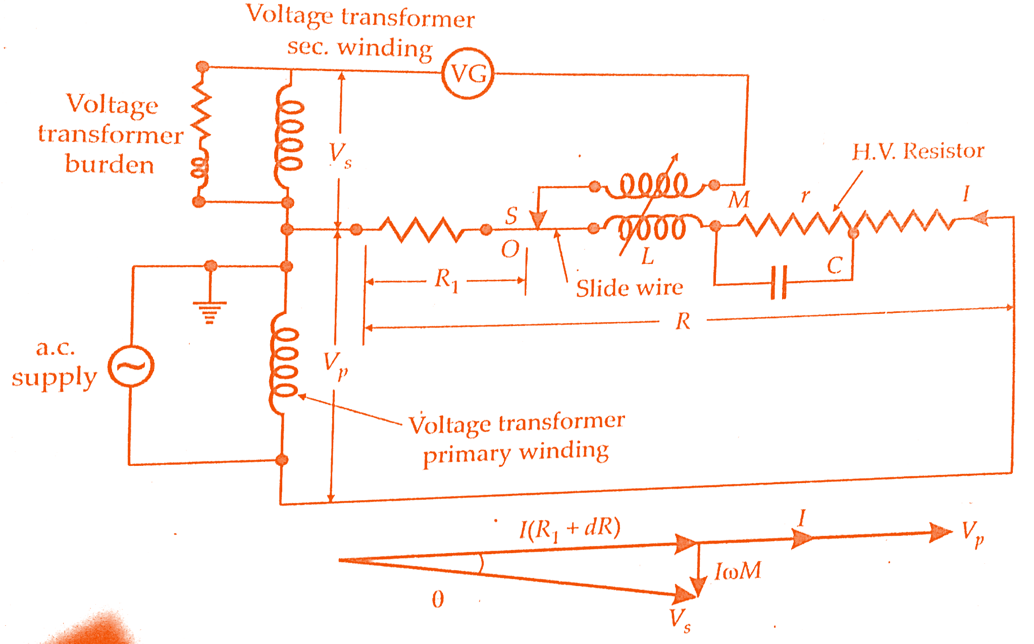
The lower part of the divider consists of a Fixed resistor in series with a side-wire S, and the upper part consists of a shielded, high voltage resistor in series with the primary of a variable mutual inductor M.
A capacitor C shunts a small part r of the upper part of the divider.VG is a vibration galvanometer.The resistances are chosen so nominally that the nominal ratio of the test transformer is equal to R/R1.
L is the primary winding inductance of the mutual inductor and will cause phase error in the divider.The capacitor C compensates for this error in the following manner.The impedance divider is the whole divider is:
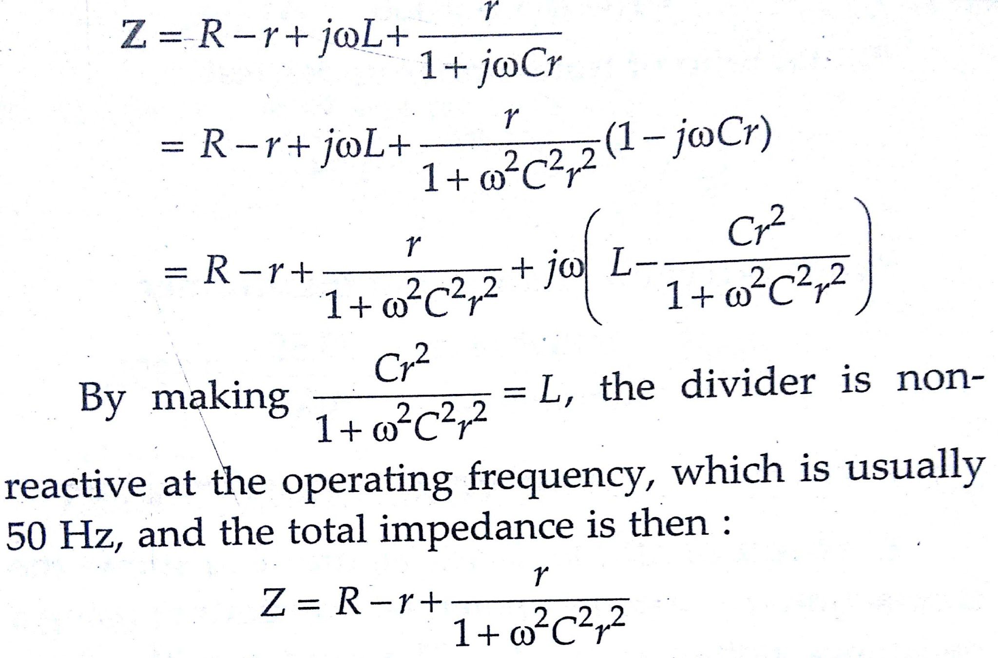
The term ω²C²r² is normally small compared with unity and may be neglected so that the impedance of the divider is equal to R. If this term is not negligible, the resistance of the upper part of the divider can be increased by a small amount to correct for it at the operating frequency.
In carrying out the test, the contacts on the slide-wire and the mutual inductor are adjusted until the vibration galvanometer gives no deflection.
The phasor diagram corresponding to the balanced condition is shown in the below figure, in which I=Vp/R is the current in the divider.The phase angle θ of the test transformer is small so that
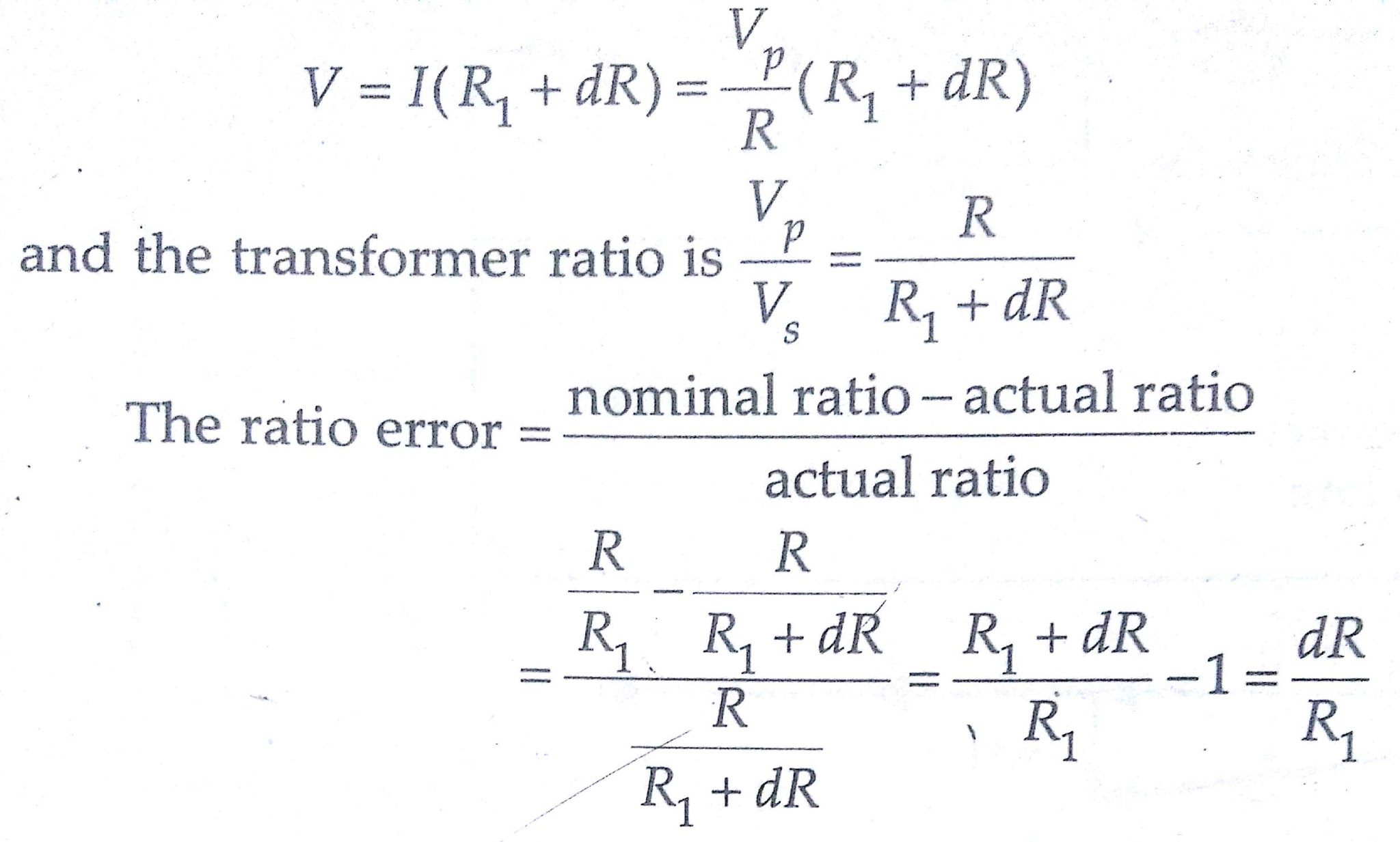
The slide-wire can, therefore, be calibrated directly in values of ratio error.
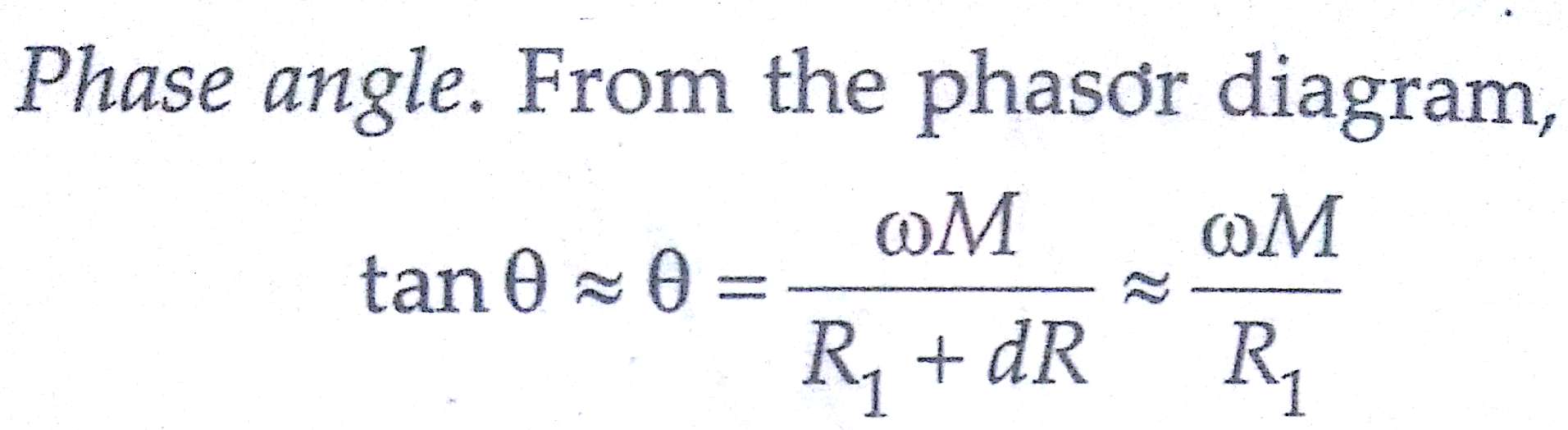
and the mutual inductor can be calibrated directly in terms of phase angle. Special shielding arrangements have to be adopted for the high voltage resistor. If it is surrounded by a simple earthed shield, the capacitance currents flowing between the resistor and shield can cause serious errors.
Such errors can be reduced by keeping the resistance of the divider as low as possible, and a value of 20 Ω/V is commonly adopted.The method of shielding is shown in high voltage testing.
The divider is broken into a number of sections, each enclosed in its own screen, and each screen is held at the mid-potential of the section it encloses by means of an auxiliary divider. There is, therefore, a considerable reduction in the capacitance current from the divider to the shield.
It is not practical to construct resistance dividers suitable for voltage transformer testing at voltages much above 40 kV; the use of a capacitance divider is preferable at higher voltages.
2)Testing Methods employing capacitance dividers :
A wide variety of methods of testing voltage transformers with the aid of capacitance dividers have been used.The figure below gives the connections of a method of testing potential transformers using capacitance voltage dividers.
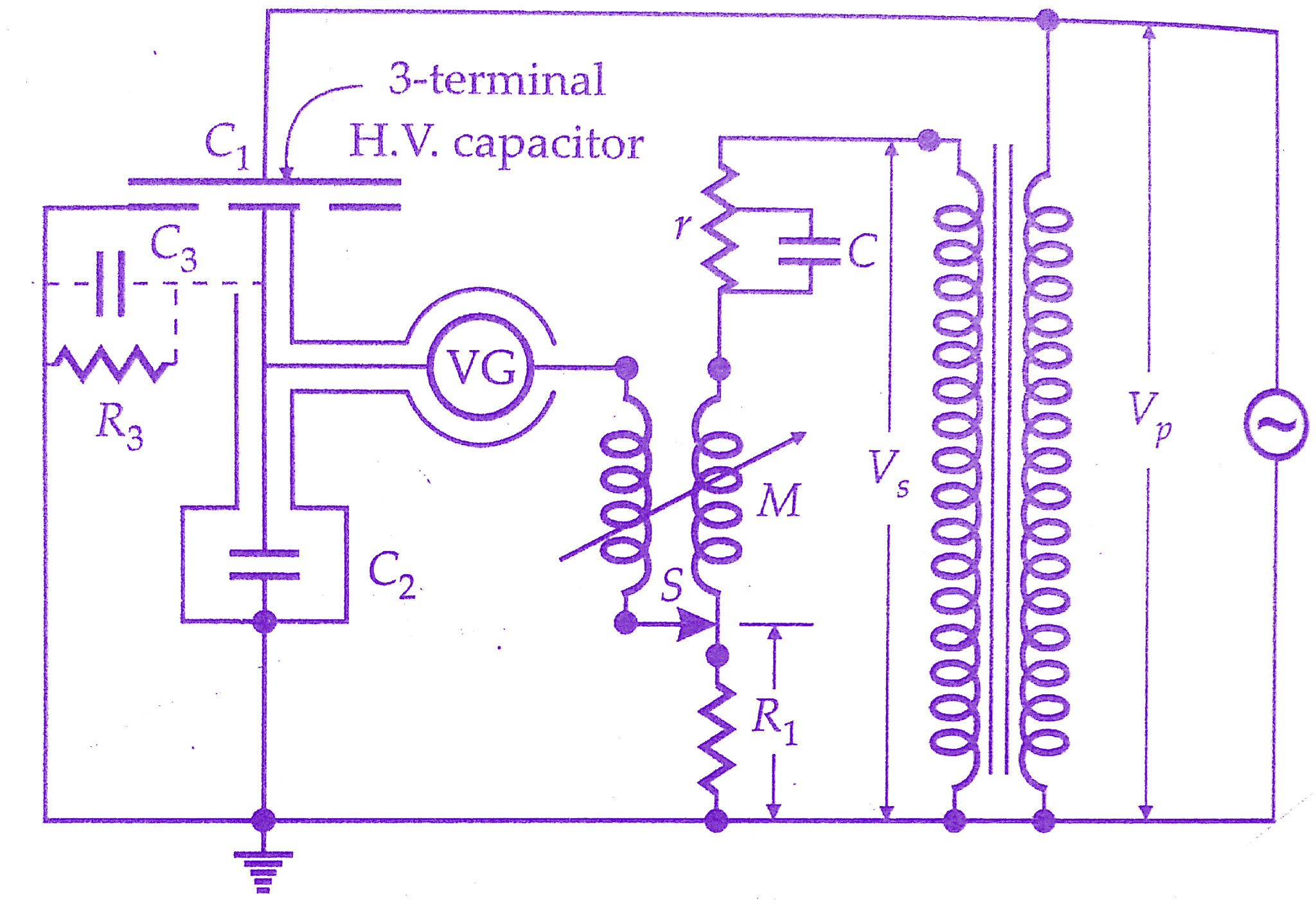
C₁ is a high voltage, compressed gas, three terminal capacitor of value 10pF and C2 is a high quality mica capacitor having a very small power factor.One of the difficulties with capacitance dividers is the existence of the capacitance C3 of the low voltage electrode and guard ring of C1.
This capacitance is often associated with a loss resistance R3, and it is therefore important that the value of the mica capacitor C3 should be large so that C2 + C3 and R3 have a negligible power factor.
The capacitance between the h.v. and l.v. electrodes of C1 is loss-free; hence the phase error of the divider, which should be negligible, is determined by C2 shunted by C3 and R3.There is, therefore, a restriction on the minimum value of C2 and on the minimum ratio of the divider.
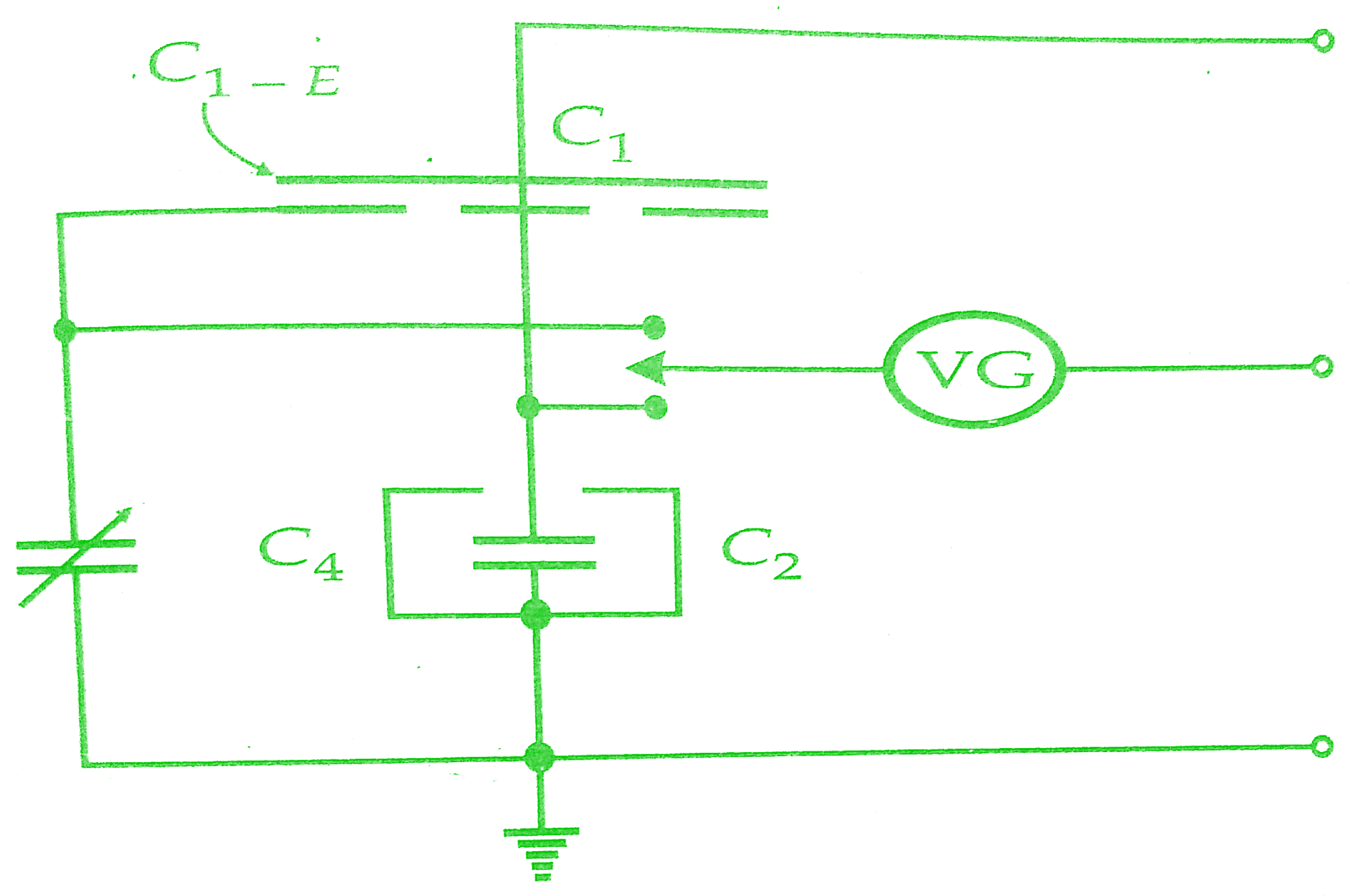
This difficulty can be overcome by the modification shown in Fig. 10.33, in which the guard ring is connected to earth through a capacitor C4 which is adjusted so that C1/C2=C3/C4.The guard ring is then at the same potential as the low-voltage electrode.
A resistance divider having a ratio of 10/1 is connected across the secondary Winding of the potential transformer under test. This divider incorporates a variable potential slide-wire S and mutual inductor M for ratio and phase-angle adjustment. It is similar to the arrangement used in the resistance divider equipment previously discussed.
C and r are used to compensate for the primary inductance of the mutual inductor M so that the divider is non-reactive at the test frequency.The slide-wire S and the mutual inductor can be calibrated to read ratio error and phase angle directly.
The adoption of a 10/1 ratio in the measuring resistance divider permits ratio errors of either. sign to be measured. It has the added advantage that the ratio of the capacitance divider is 10 times the nominal ratio of the test transformer permitting the use of a large value of C2 and thus minimizing the effect of C3 and R3 in the simple arrangement.
The compensation of the measuring resistance divider and its zero setting can be very easily checked by comparing it with a simple 10/1 ratio resistance divider.
Clothier and medina method:
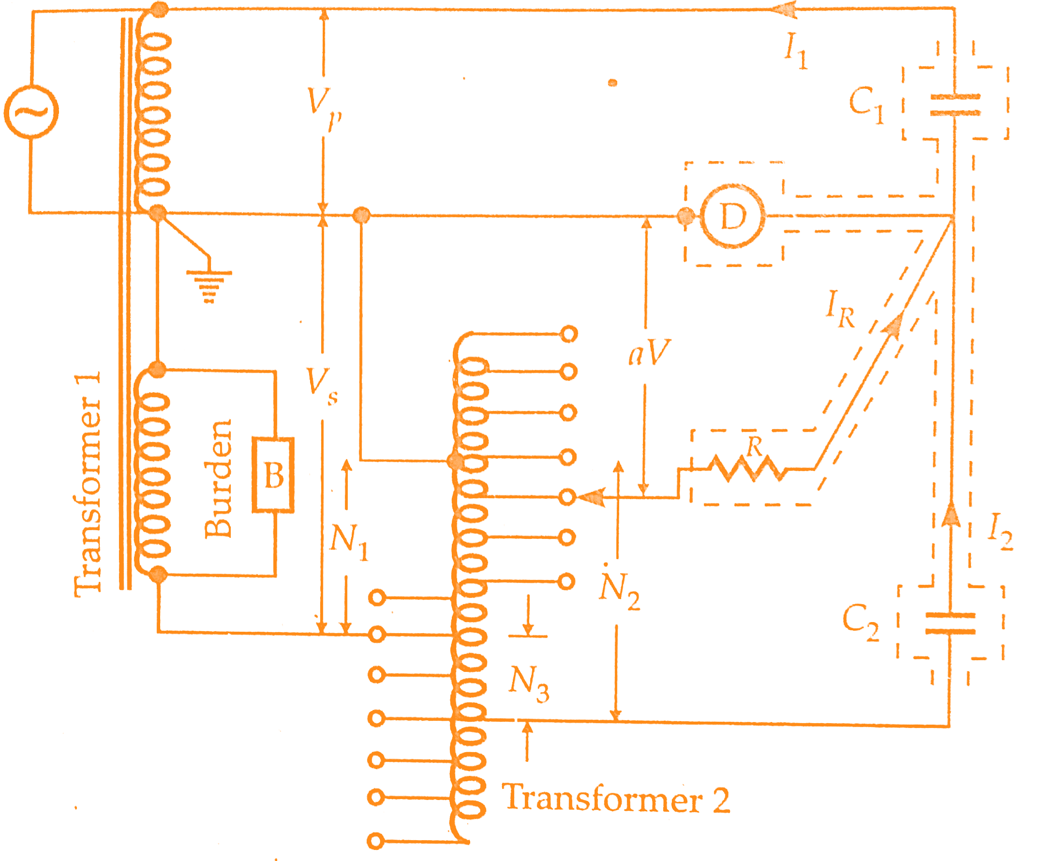
This method has been developed quite recently and uses a variable- tapping transformer for the measuring device.The figure below is a simplified circuit diagram.C1 and C2 are three-terminal capacitors whose ratio is equal to the nominal ratio of the test transformer 1.
The windings of transformer 1 are in series aiding.The errors in transformer 1 are balanced by means of transformer 2 whose ratio can be adjusted a little above or below unity by using decade switches to select the primary turns.
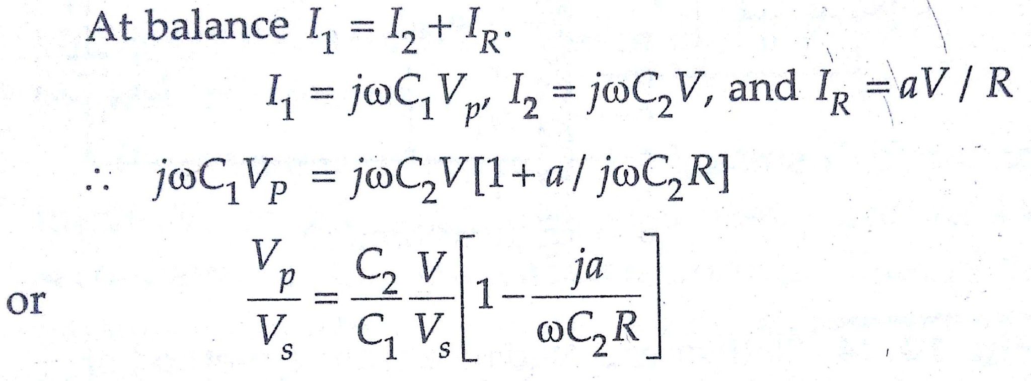
Phase-angle errors are balanced by supplying a current IR through a high resistance R to the junction of C1 and CR.IR is in phase with the secondary voltage and therefore in quadratic with the current in C2.
The value of IR is adjusted by a switch on transformer 2 using the tuned electronic detector.Since the detector voltage is zero at balance, the current in R is aV / R, where aV is the voltage across R with respect to earth and V is the voltage across C2. aV can have either sign.
If the phase angle of the auxiliary transformer is negligible, and its voltage is very nearly equal to its turns ratio, then, if N1 and N2 are primary and secondary turns on Transformer 2, and if N = N2 – N1.
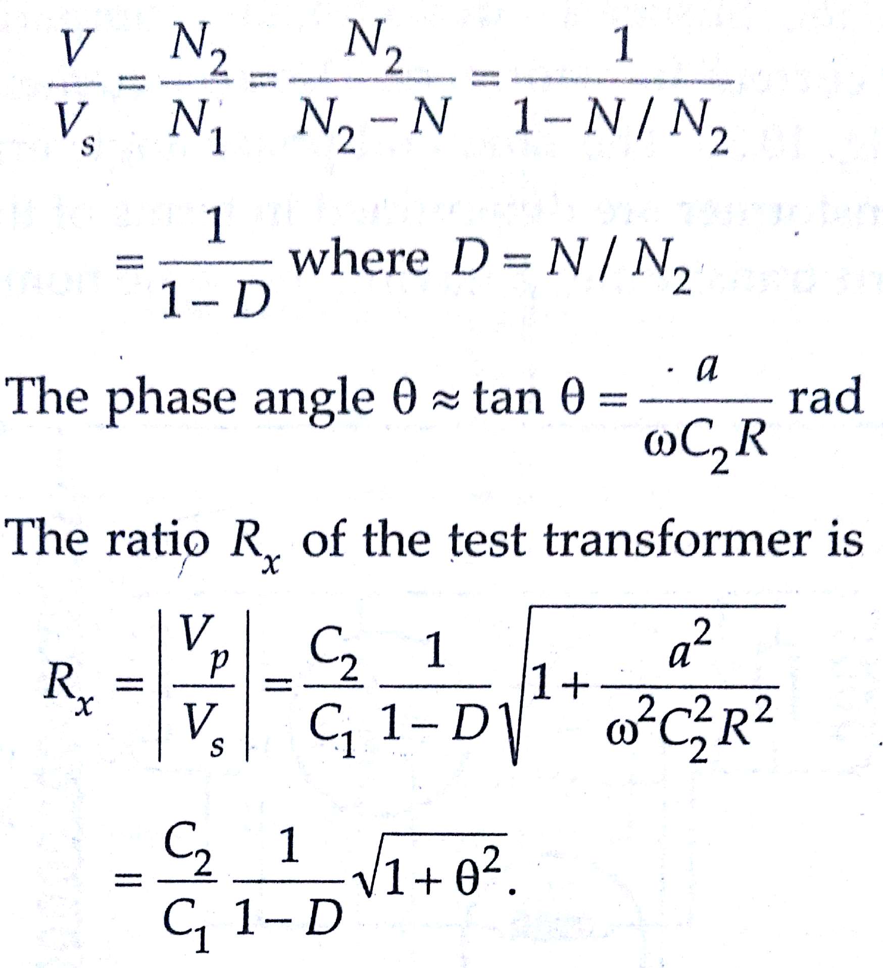
If the ratio of the capacitance divider is adjusted so that C2/C1 is equal to the nominal ratio K of the transformer, then
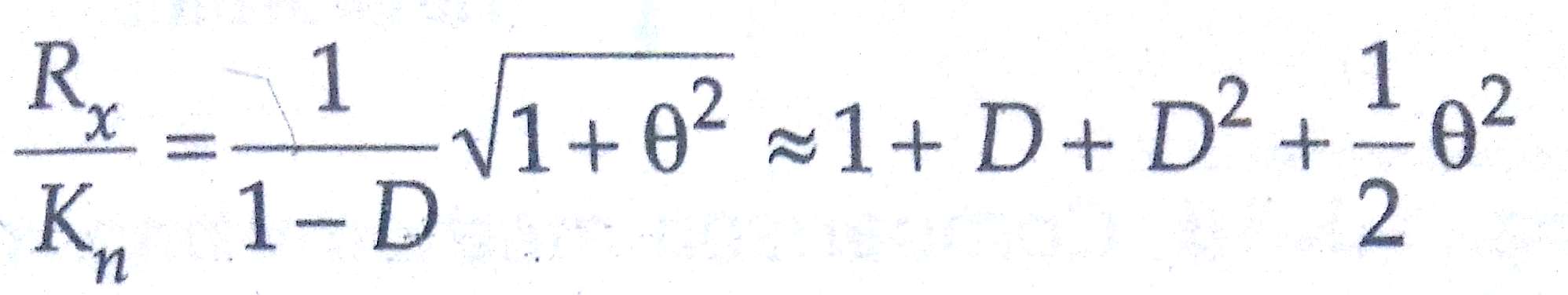
In general Rx/Kn = 1 + D gives sufficient accuracy.The accuracy of the method depends upon the auxiliary transformer 2.Its ratio is nearly unity, however, and in these conditions, it is not difficult to construct a transformer having very small ratio error and phase angle.The guard rings which constitute the third terminals of capacitors C1 and C2 are not shown in the figure below; both are connected to earth.
Comparison Methods for Testing of Potential Transformers :
1)Method using Wattmeters:
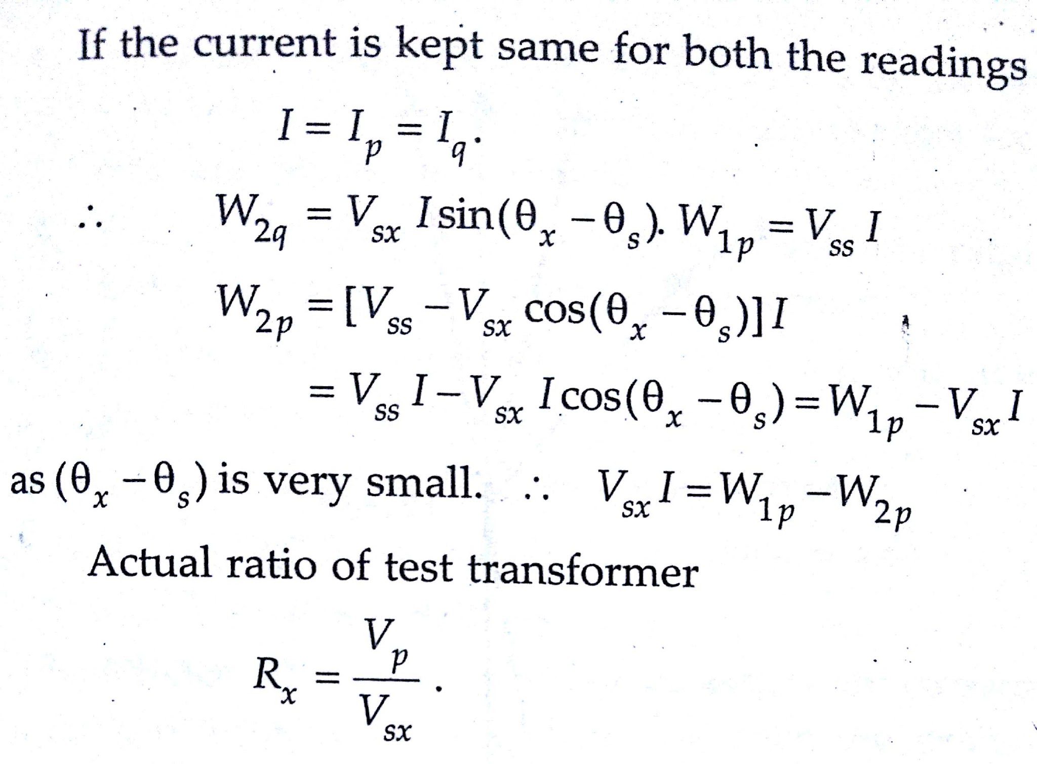
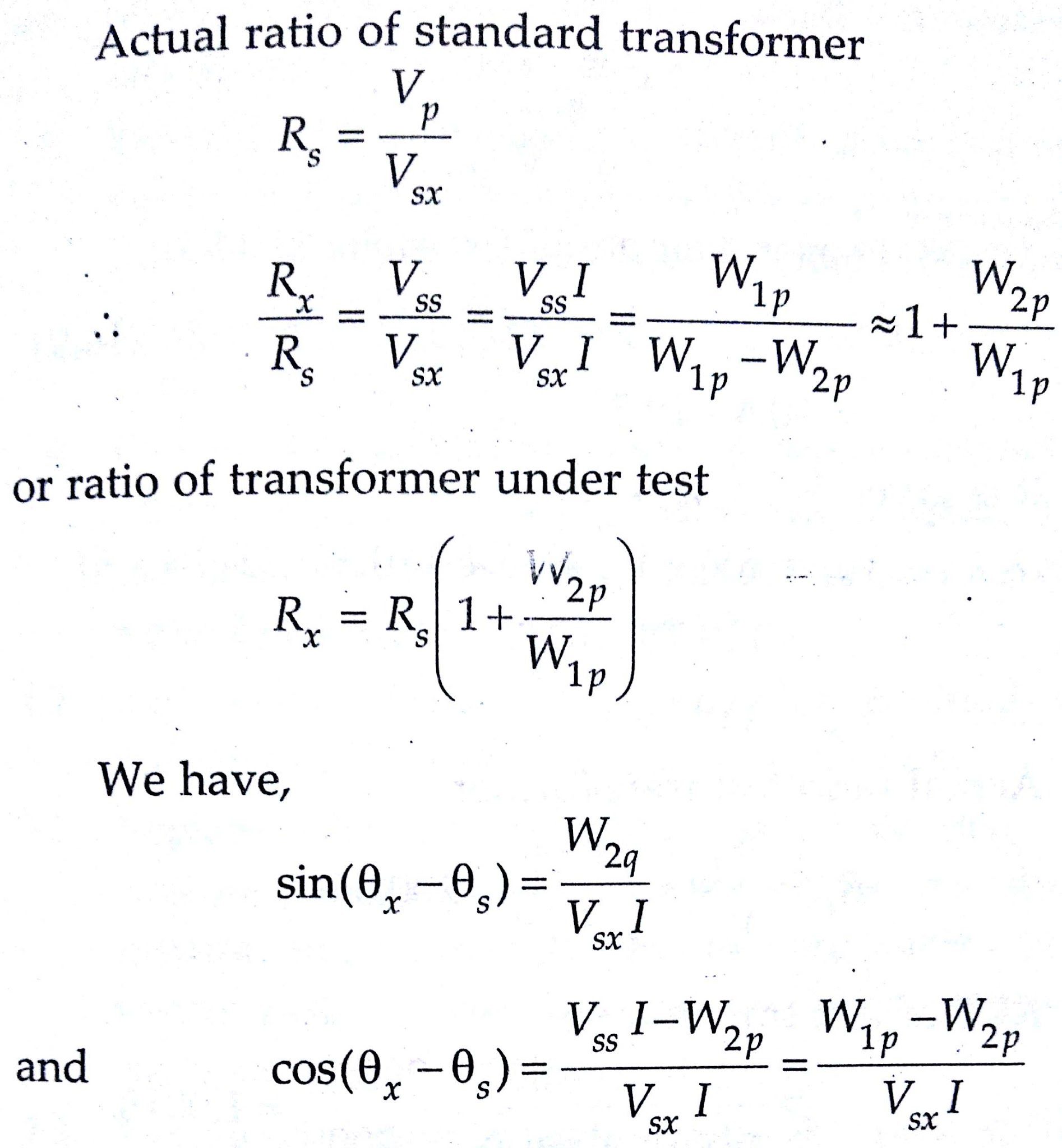
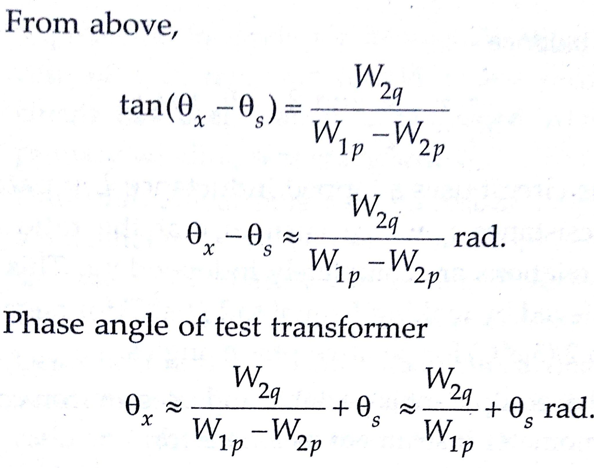
This method is analogous to Silsbee’s deflectional comparison method for current transformers. The arrangement is shown in the below figure.The ratio and phase angle errors of a test transformer are determined in terms of those of a standard transformer S having the same nominal ratio.
The two transformers are connected with their primaries in parallel. A burden is put in the secondary circuit of test transformer.W1 is a wattmeter whose potential coil is connected across the secondary of the standard transformer.
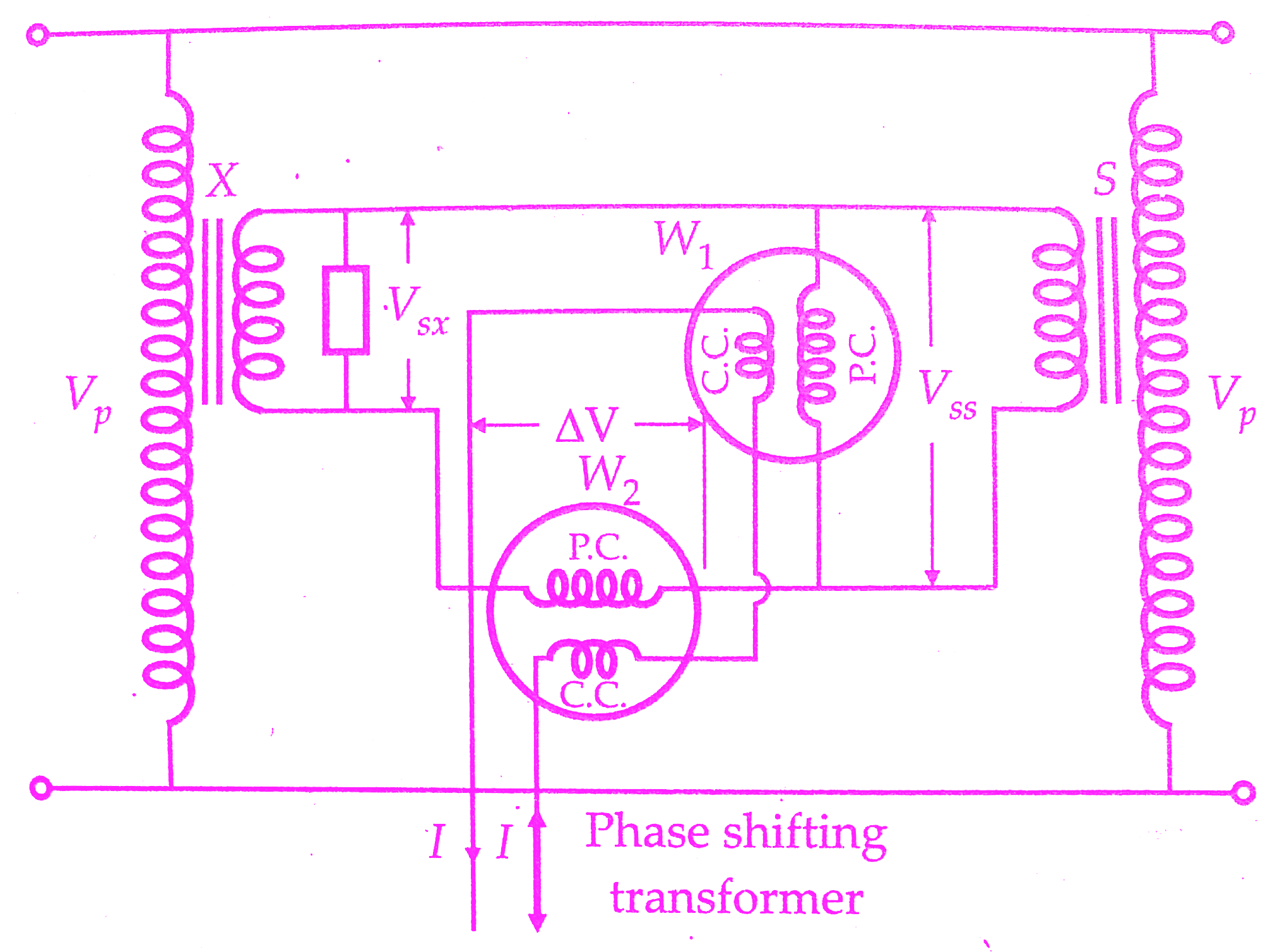
The pressure coil of wattmeter W2 is so connected that a voltage ∆V which is the difference between secondary voltages of standard and test transformers, is impressed across it. The current coils of the two wattmeters are connected in series and are supplied from a phase shifting transformer. They carry a constant current I.
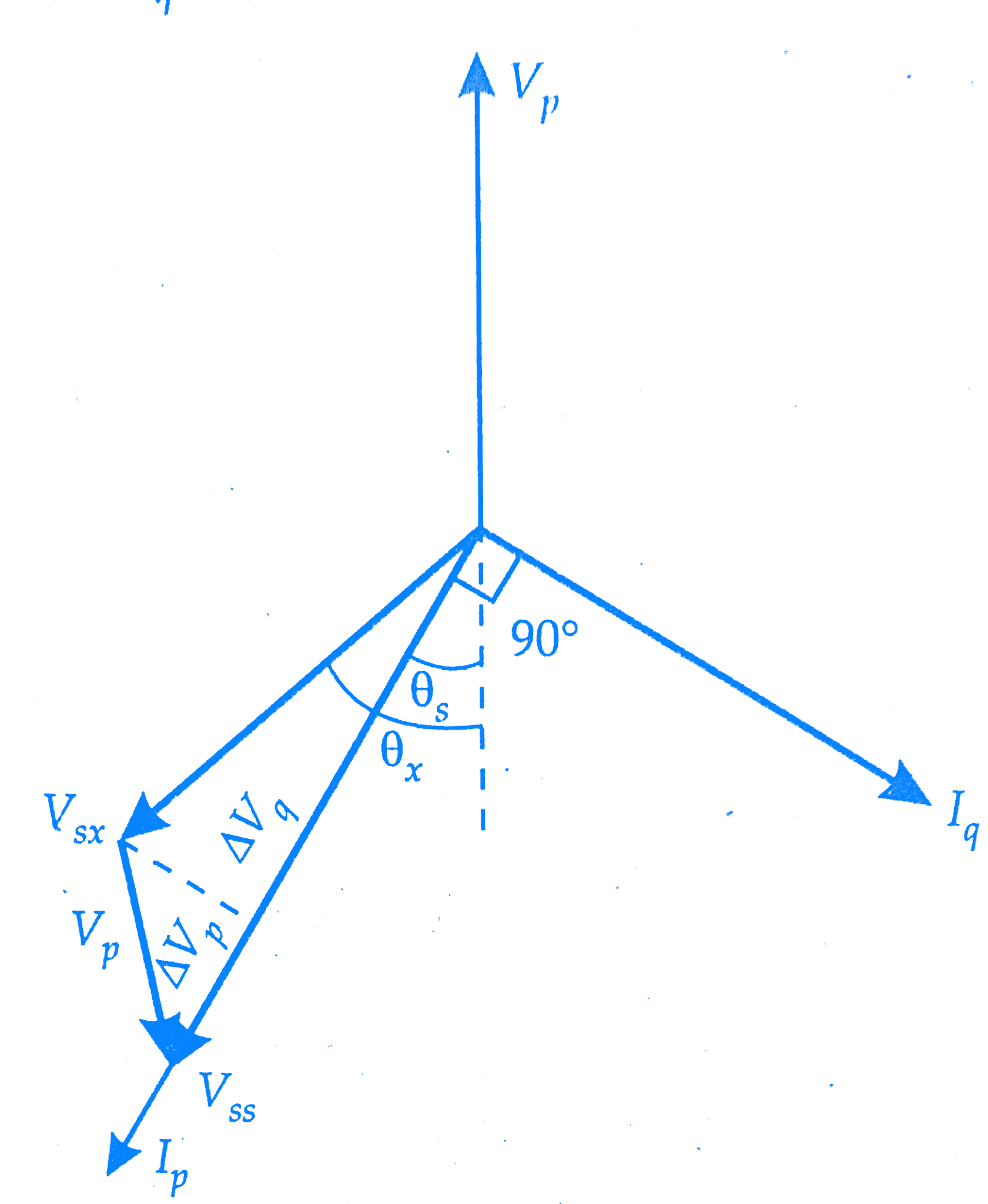
1.The phase of the current I is so adjusted that the wattmeter W1 reads zero. Under these conditions current, I is in Vss quadrature with voltage Vss.The position of current phasor for this case is shown in the below figure as Iq .
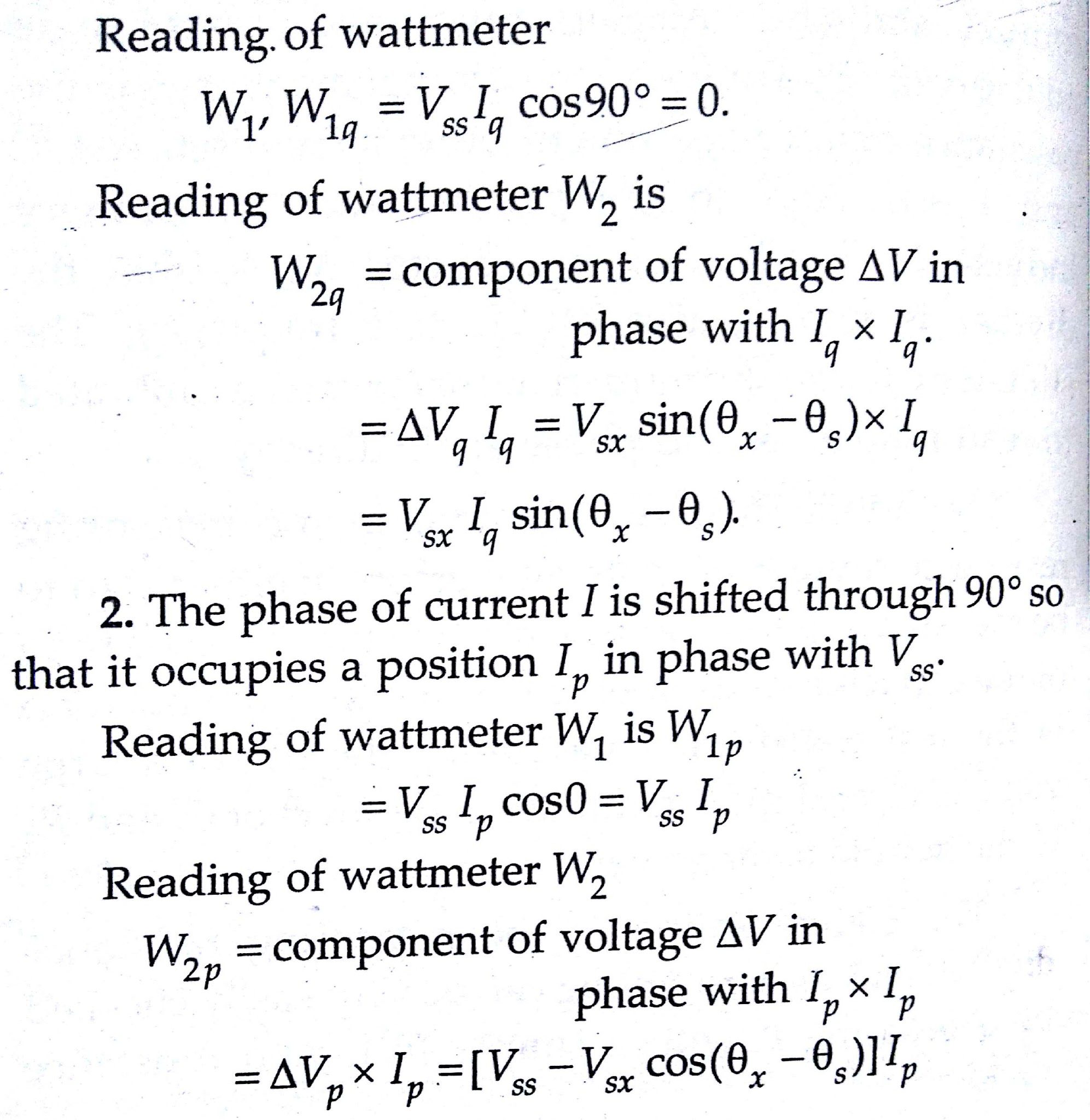
Wattmeter W2 should have a very low voltage range since only a small voltage AV is impressed upon its pressure coil.
2)Clothier and Medina comparison method:
A simplified diagram of the test circuit devised by Clothier and Medina is shown in the below figure.The primaries of the two transformers are connected in parallel and facilities are provided for fine adjustments of magnitude and phase of the secondary voltage of standard transformer until it equals that of the test transformer.
Ratio balance is affected by adjustment of primary turns N, of an autotransformer connected to the secondary of the current transformer.The phase balance is done by adjustment of a resistance r through which current flows, this current being in quadrature with the secondary voltage.
The sign of the secondary voltage is selected by a reversing switch.Adjustments of resistance r can be made in steps of 1 in 10.000 in ratio and 0.1′ in phase.
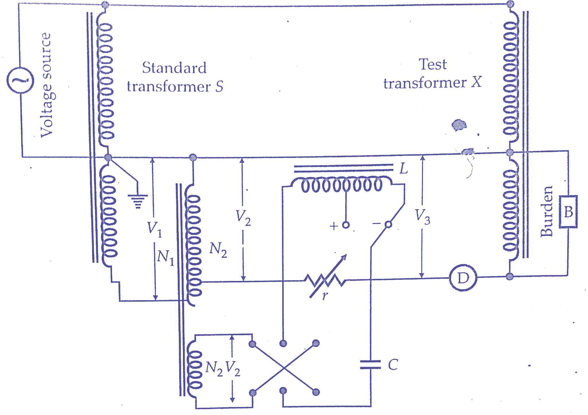
The circuit uses a tapped inductance L in parallel with resistance r, which ensures that the ratio and phase relations are completely independent.This can be achieved by mistaking L equal 2/(ω²C) for negative and to 2/(3ω²C) for positive phase angles.This equipment is portable and uses an iron cored dynamometer instrument as a detector.
Conclusion:
So far we have learnt testing of potential transformers.You can download this article as pdf, ppt.
Comment below for any Queries.