What are Potential Transformers?
Potential transformers are used to operate voltmeters, the potential coils of wattmeters and relays from high voltage lines.The primary winding of the transformer is connected to the line carrying the voltage to be measured and the voltage circuit is connected across the secondary winding.
The construction of potential transformer is quite similar to that of a power transformer but the loading of a potential transformer is always small, sometimes only a few volt-ampere.The secondary winding is designed so that a voltage of 100 to 120 V is delivered to the instrument load.The normal secondary voltage rating is 110 V.
Must Read:
Construction of Potential Transformers:
The design and construction of potential transformers are basically the same as those of power transformers but there are few major points of difference :
(i) Power transformers are designed keeping in view the efficiency, regulation and cost.The cost being reduced by using small core and conductor sizes.In designing a potential transformer, the economy material is not a big consideration and the transformers are designed to give desired performance i.e. constancy of ratio and smallness of phase angle:
Compared to a power transformer, a potential transformer has larger core and conductor sizes. Economic designs may lead to large ratio and phase angle errors which are undesirable features.
(ii) The output of a potential transformer is always small and the size is quite large.Therefore, the temperature rise is small and hence there are no thermal problems caused by overloads as in power transformers. In fact, the loading of a potential transformer is limited by accuracy considerations while in a power transformer the load limitation is on the heating basis.
Actually, the potential transformers are able to carry loads on a thermal basis many times their rated loads.These loads range from 2 to 3 times for low voltage potential transformers and up to 30 or more times for some high voltage transformers.
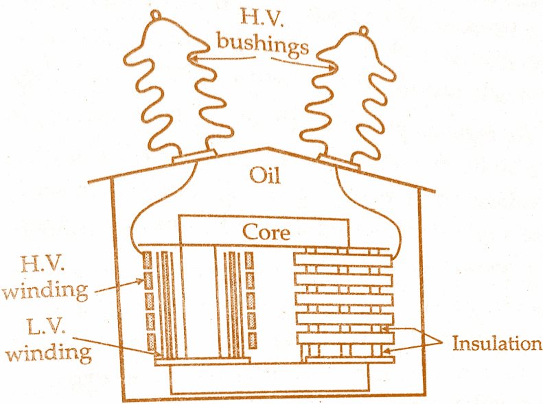
Core: The core may be of shell or core type of construction. Shell type of construction is normally only used for low voltage transformers.Special precautions should be taken to assemble and interleave the core laminations so that the effect of air gaps at the joints may be minimized.
Windings: The primary and secondary windings are coaxial to reduce the leakage reactance to the minimum.In order to simplify the insulation problems, the low voltage winding (secondary) is put next to the core.The primary winding may be a single coil in low voltage transformers but must be subdivided into a number of short coils in high voltage transformers-in order to reduce the insulation needed between coil layers.
Must Read:
Insulation: Cotton tape and varnished cambric are used as insulation for coil construction. Hard libre separators are used between coils. At low voltages, the transformers are usually filled without compound but potential transformers for use at voltages above 7 kV are oil immersed.Dry type, porcelain insulated transformers have been developed on the continent for use up to 45 kV.
Bushings: Oil-filled bushings are usually’used for oil filled potential transformers as this minimizes the overall size of the transformer.Two bushings are used when neither side of the line is at ground potential. Some potential transformers, connected from line to neutral of grounded neutral systems, have only one high voltage bushing.
It is pertinent to point out here that a current transformer needs only one bushing as leads from the two ends of the primary winding are brought through the same insulator since there is only a small voltage between them, thus saving the expense of another high voltage insulator.
A 2-winding single phase potential transformer shown in the below figure.
High Voltage Potential Transformers:
Conventional type potential transformers used for high voltages of 110 kV and above are very large in size and costly to build because of insulation requirements.For example, a 110 kV potential transformer has an overall height of about 7.5 meters and weighs nearly 5 tonnes. This is a very unwieldy size and also the materials utilized in the construction of potential transformer are very uneconomically utilized.
Recently there has been a development in the design and construction of potential transformers which has resulted in considerable reduction in size and cost of transformers.Two designs have been developed which eliminate the high voltage lead in bushings.The elimination of bushings reduces the size and cost of transformers.
Must Read:
These designs are intended to measure line to ground voltages in a three phase system. The designs employ
(i) Insulated casing: The transformer is built entirely in an oil filled high voltage insulator. This results in economy in space and material.
(ii) Moulded rubber potential transformer: Recent developments in the synthetic rubber industry have introduced the moulded rubber potential transformer, replacing the insulating oil and porcelain bushings for some applications.This unit is less expensive than the conventional oil filled P.T., and since the bushings are made of moulded rubber, the difficulties caused due to porcelain breakage are eliminated.
(iii)Cascaded transformers: In a cascaded arrangement, the voltage is divided among a number of transformers. Suppose the voltage is divided among N transformers and, therefore, each transformer will take 1/N of total voltage. In this way, each requires insulation corresponding to the lower voltage, with a consequent saving in space and material.The chief application of cascade arrangement is to increase voltage rating of dry type units.
Must Read:
Protection of Potential Transformers:
Potential transformers can be continuously operated at 1.2 times the rated voltage. A short circuit on the secondary side of a potential transformer can lead to complete damage of the transformer. In order to protect the power system against short circuits in the potential transformers, fuses are used on the primary (high voltage) side. Fuses are used in the secondary side to protect the P.T. against faulty switching and defective earthing.
Capacitive Potential Transformers:
At voltages above about 100 kV (phase) the conventional electromagnetic type of potential transformer becomes expensive owing to insulation requirements. A less expensive alternative is capacitive voltage transformer. This consists of a capacitance potential divider used in conjunction with a conventional auxiliary transformer.The capacitance potential divider steps down the voltage to be measured (say to about 10 kV).
The capacitance divider output voltage is further stepped down by the auxiliary transformer to the desired secondary voltage (say 110 V). The auxiliary transformer consists of an inductance which may consist wholly or partly of leakage inductance of the windings of auxiliary transformer.
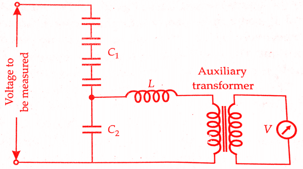
The value of this inductance L may be adjusted to equal 1/ω²(C₁ + C₂) so that the voltage drop due to the current drained from the divider is largely compensated.Thus the overall voltage transformation ratio is independent of burden.The overall ratio is the product of the divider and transformer ratios.
In practice, however, the compensation is not complete because of the losses in the inductance and also due to small changes in frequency which might occur. Nevertheless, the performance of capacitor – voltage transformers is not much inferior to that of the electromagnetic type of potential transformers and provided the current in the primary of the auxiliary transformer does not exceed about 10% of that in the divider.
Must Read:
Characteristics of Potential Transformers:
1)Effect of secondary current or VA:
If we increase the secondary burden. the secondary current is increased, and therefore, the primary current increases. Both primary and secondary, voltage drops increase and thus for a given value of Vp, the value of Vs decreases and hence the actual ratio increases as the burden increases. The ratio error increases becoming more negative with increase in burden. This variation of ratio error is almost linear with the change in burden.
With regard to the phase angle, the voltage Vp is more advanced in phase because of increased voltage drops with the increase in secondary burden.The phasor Vs reversed is retarded in phase owing to increase in second, winding voltage drops.Thus with the increase in burden. the phase angle between Vp and Vs reversed increases becoming more negative.
2)Effect of power factor of secondary burden:
If the power factor of secondary circuit burden is reduced angle ∆ is increased. This makes current Ip shift towards current I0. The voltage Vp and Vs come more nearly into phase with Ep and Es respectively since the Voltage drops are almost constant. The result is an increase in Vp relative to Ep. But Vp is constant and, therefore, Ep reduces relative to Vp.
The voltage Vs reduces relative to Es. Therefore, the transformation ratio increases as the power factor of secondary burden reduces.Now With the decrease in power factor, Vs is advanced in phase and Vp retarded in phase, the phase angle (-ve) reduces with the decrease in secondary power factor.
3)Effect of frequency:
For a constant voltage the flux is inversely proportional to frequency, Increase in frequency reduces the flux and, therefore Im and Ie are decreased and, therefore, the voltage ratio decreases. The decrease is not so much, as with increase in frequency the leakage reactance increases and, therefore, leakage reactance drops are increased giving an increase in the ratio.
Thus changes in voltage ratio because of change in frequency are dependent upon relative values of In and leakage reactances since the effects produced by them oppose each other. As regards phase angle error, both effects due to increase in frequency advance Vp and the increase in secondary reactance retards Vs and therefore, the phase angle is increased as the frequency increases.
Must Read:
4)Effect of primary voltage:
There is no wide variation of the supply voltage to which the primary winding of the potential transformer is connected. Therefore the study of variation of ratio and phase angle errors with supply voltage is of no importance.
Conclusion:
Now here we have learnt Construction & Working of Potential Transformers. You can download this article as pdf, ppt.
Comment below for any Queries.