Measurement of Self Inductance By Anderson’s Bridge:
Anderson’s Bridge, in fact, is a modification of Maxwell’s inductance capacitance bridge. In Anderson’s Bridge, the self inductance is measured in terms of a standard capacitor.
Understanding Self-Inductance: Before delving into Anderson’s Bridge, let’s grasp the concept of self-inductance. When the current flowing through a coil changes, it creates a magnetic field around the coil. This magnetic field then induces an opposing EMF, known as self-induced EMF, which resists the change in current. The self-inductance (L) of a coil is a measure of this effect and is typically measured in henrys (H).
Introducing Anderson’s Bridge: Anderson’s Bridge is a modified version of the Wheatstone bridge, a classic circuit used for measuring resistance. However, instead of measuring resistance, Anderson’s Bridge is designed to measure inductance. The bridge consists of four arms, three of which are resistors and one is the inductor whose self-inductance needs to be measured.
Working Principle: The principle behind Anderson’s Bridge lies in achieving a balanced condition, where there is no current flowing through the galvanometer. This balanced state is achieved when the ratio of the impedances of the inductor (ZL) and the known resistor (ZR) in one arm is equal to the ratio of impedances of the other two resistors (Z1 and Z2) in the adjacent arm. Mathematically, this can be expressed as:
ZR/ZL=Z2/Z1
Where:
- ZL is the impedance of the inductor (jωL, where ω is the angular frequency and L is the inductance).
- ZR is the impedance of the known resistor.
- Z1 and Z2 are the impedances of the resistors in the adjacent arm.
By adjusting the values of the known resistor and the resistors in the adjacent arm, the bridge can be balanced, allowing for the calculation of the unknown self-inductance.
Measurement Process:
- Set up the Anderson’s Bridge circuit with the inductor in one arm and the known resistor in another arm.
- Gradually vary the values of the resistors in the adjacent arm while observing the galvanometer. When the galvanometer shows no deflection, the bridge is in a balanced state.
- At this balanced state, the ratios of impedances on both sides of the bridge equation are equal, enabling the calculation of self-inductance using the formula:
L=Z2R/Z1*Z2
Anderson’s Bridge is usefully applicable for precise measurement of self inductance over a very wide range of values. The below figure shows the connections and the phasor diagram of the bridge for balanced conditions.
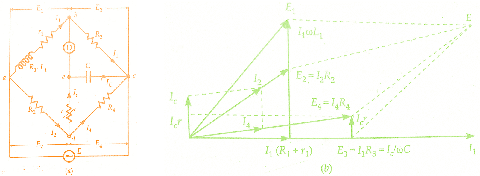
Let L1 = self-inductance to be measured,
R1 = resistance of self-inductor,
r = resistance connected in series with self-inductor,
r, R2, R3, R4 = known non-inductive resistances, and
C = fixed standard capacitor
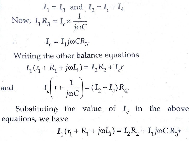
At balance,
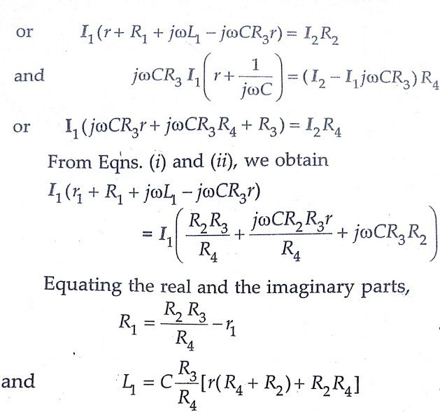
An examination of balance equations reveals that to obtain easy convergence of balance, alternate adjustments of r1 and r should be done as they appear in only one of the two balance equations.
Advantages of Anderson’s Bridge:
1. In case adjustments are carried out by manipulating control over r1 and r, they become independent of each other. This is a marked superiority over sliding balance conditions met with low Q coils when measuring with Maxwell’s bridge. A study of convergence conditions would reveal that it is much easier to obtain balance in the case of Anderson’s bridge than in Maxwell’s bridge for low Q-coils.
2. A fixed capacitor can be used instead of a variable capacitor as in the case of Maxwell’s bridge.
3. Anderson’s Bridge may be used for accurate determination of capacitance in terms of inductance.
Disadvantages of Anderson’s Bridge :
1. The Anderson’s bridge is more complex than its prototype Maxwell’s bridge. The Anderson’s bridge has more parts and is more complicated to set up and manipulate. The balance equations are not simple and in fact are much more tedious.
2. An additional junction point increases the difficulty of shielding the bridge.
Conclusion:
In this, we have learnt measurement of self inductance by Anderson’s bridge.You can download this article as pdf, ppt.
Share and comment what you feel!