What are AC Bridges?
Alternating current bridge methods are of outstanding importance for measurement of electrical quantities. Measurement of inductance, capacitance, storage factor, loss factor may be made conveniently and accurately by employing ac bridge networks.
The AC bridge is a natural outgrowth of the Wheatstone bridge.An ac bridge, in its basic form, consists of four arms, a source of excitation, and a balance detector.
In an ac bridge, each of the four arms is an impedance, and the battery and the galvanometer of the Wheatstone bridge are replaced respectively by an ac source and a detector sensitive to small alternating potential differences.
The usefulness of ac bridge circuits is not restricted to the measurement of unknown impedances and associated parameters like inductance, capacitance, storage factor, dissipation factor etc.
These circuits find other applications in communication systems and complex electronic circuits.Alternating current bridge circuits are commonly used for phase shifting, providing feedback paths for oscillators and amplifiers, filtering out undesirable signals and measuring frequency of audio signals.
For measurements at low frequencies, the power line may act as the source of supply to the bridge circuits.For higher frequencies, electronic oscillators are universally used as bridge source supplies. These oscillators have the advantage that the frequency is constant, easily adjustable, and determinable with accuracy.
The waveform is very close to a sine wave, and their power output is sufficient for most bridge measurements.A typical oscillator has a frequency range of 40 Hz to 125 kHz with a power output of 7 W.
The detectors commonly used for ac bridges are :
(i) Headphones,
(ii) Vibration galvanometers, and
(iii) Tuneable amplifier detectors.
Headphones are widely used as detectors at frequencies of 250 Hz and over upto 3 or 4 kHz. They are most sensitive detectors for this frequency range. When working at a single frequency a tuned detector normally gives the greatest sensitivity and discrimination against harmonics in the supply.
Vibration galvanometers are extremely useful for power and low audio frequency ranges.Vibration galvanometers are manufactured to work at various frequencies ranging from 5 Hz to 1000 Hz but are most commonly used below 200 Hz as below this frequency they are more sensitive than the headphones.
Tuneable amplifier detectors are the most versatile of the detectors. The transistor amplifier can be tuned electrically and thus can be made to respond to a narrow bandwidth at the bridge frequency. The output of the amplifier is fed to a pointer type of instrument. This detector can be used, over a frequency range of 10 Hz to 100 kHz.
For ordinary ac bridge measurements of inductance and capacitance, a fixed frequency oscillator of 1000 Hz and output of about 1 W is adequate. For more specialised work continuously variable oscillators are preferable with outputs up to 5 W. The high power may be necessary on some occasions, but in practice, it is better to limit the power supplied to the bridge.
Another practice which is usually followed is to use an untuned amplifier detector. The balance detection is sensed both orally by headphones, and visually by a pointer galvanometer having a logarithmic deflection (In order to avoid damage to the galvanometer which may be caused by unbalance).
General Equation for AC Bridge Balance:
The below figure shows a basic ac bridge. The four arms of the bridge are impedances Z1,Z2,Z3 & Z4.
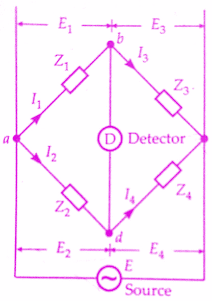
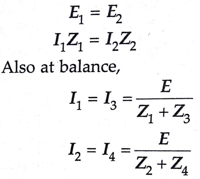
The conditions for the balance of bridge require that there should be no current through the detector. This requires that the potential difference between points b and d should be zero. This will be the case when the voltage drop from a to b equals to voltage drop from a to d, both in magnitude and phase. In complex notation we can, thus, write :
On Substitutions we get,
Z1 Z4 = Z2 Z3
or when using admittances instead of impedances
Y1 Y4 = Y2 Y3
Above two equations represent the basic equations for the balance of an ac bridge. Equation Z1 Z4 = Z2 Z3 is convenient to use when dealing with series elements of a bridge while Equation Y1 Y4 = Y2 Y3 is useful when dealing with parallel elements.
Equation Z1 Z4 = Z2 Z3 states that the product of impedances of one pair opposite arms must equal the product of impedances of the other pair of opposite arms expressed in complex notation.This means that both magnitudes and the phase angles of the impedances must be taken into account.
Considering the polar form, the impedance can be written as Z = Z∠θ, where Z represents the magnitude and θ represent the phase angle of the complex impedance.Now that equation can be re-written in the form
(Z1∠θ1)(Z4∠θ4) = (Z2∠θ2)(Z3∠θ3)
Thus for balance, we must have,
Z1 Z4 ∠θ1 + θ4 = Z2 Z3 ∠θ2 + θ3
The above equation shows that two conditions must be satisfied simultaneously when balancing an ac bridge.The first condition is that the magnitude of impedances satisfies the relationship :
Z1 Z4 = Z2 Z3
The second condition is that the phase angles of impedances satisfy the relationship :
∠θ1 + θ4 = ∠θ2 + θ3
The phase angles are positive for an inductive impedance and negative for capacitive impedance.
If we work in terms of rectangular coordinates, we have
Z1= R1 + jX1 ; Z2= R2 + jX2
Z3= R3 + jX3 and Z4= R4 + jX4
For balance, Z1 Z4 = Z2 Z3
or (R1 + jX1)(R4 + jX4) = (R2 + jX2)(R3 + jX3)
or R1 R4 – X1 X4 + j(X1R4 + X4R1) = R2 R3 – X1 X4 + j(X2R3 + X3R2)
The above equation is a complex equation and a complex equation is satisfied only if real and imaginary parts of each side of the equation are separately equal. Thus, for balance,
R1 R4 – X1 X4 = R2 R3 – X1 X4
X1R4 + X4R1 = X2R3 + X3R2
Thus there are two independent conditions for balance and both of them must be satisfied for the ac bridge to be balanced.
General Form of AC Bridges:
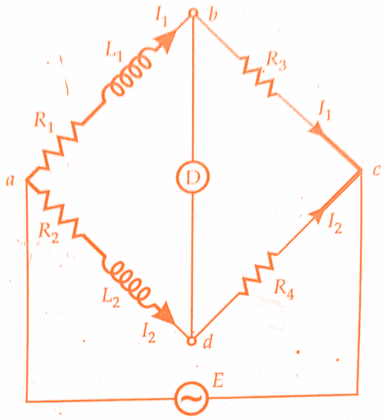
As an example let us consider, the ac bridge circuit in the below figure. R3 and R4 are non-inductive resistances, L1 and L2 are inductances of the negligible resistance and R1 and R2 are non-inductive resistors. Therefore at balance,
Z1 Z4 = Z2 Z3
or (R1 + jωL1) R4 = (R2 + jωL2) R3
Equating the real and imaginary parts separately, we have,
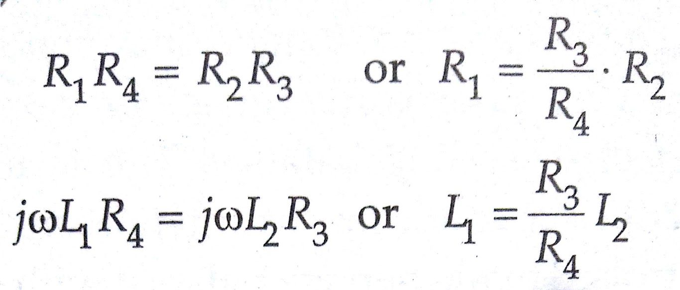
Thus if L1 and R1 are unknown, the above bridge may be used to measure these quantities in terms of R2, R3, R4 and L2.We may deduce several important conclusions from the above simple example. They are :
1.Two balance equations are always obtained for an ac bridge circuit.This follows from the fact that for balance in an ac bridge, both magnitude and phase relationships must be satisfied.This requires that real and imaginary terms must be separated, which give two equations to be satisfied for balance.
2.The two balance equations enable us to know two unknown quantities.The two quantities are usually a resistance and an inductance or a capacitance.
3.In order to satisfy both conditions for balance and for the convenience of manipulation, the bridge must contain two variable elements in its configuration. For greatest convenience, each of the balance equations must contain one variable element, and one only. The equations are then said to be independent.
In the ac bridge of below figure, R2 and L2 are the obvious choices as variable elements since L2 does not appear in the expression for R1, and R2 does not figure in the expression for L1 and hence the two balance equations are independent.
The technique of balancing is to adjust L2 till a minimum indication is obtained on the detector, then to adjust R2 until a new smaller minimum indication is obtained.Then L2 and R2 are alternately adjusted until the detector shows no indication.
The process of alternate manipulation of two variable elements is rather typical of the general balancing procedures adopted in most ac bridges. When two variables are chosen such that the two balance equations are no longer independent, the ac bridge has a very poor convergence of balance and gives the effect of sliding balance.
The term Sliding Balance describes a condition of interaction between the two controls. Thus when we balance with R2, then go to R3 and back to R2 for adjustment, we find a new apparent balance.
Thus the balance point appears to move, or slide and settles only gradually to its final point after many adjustments.It may be emphasised here that in case the two balance conditions are independent, not more thane two or three adjustments of the variable elements would be necessary to obtain balance.
In case we choose the two variable components such that the two equations are not independent the balance procedure becomes laborious and time-consuming.
For example, if we choose R2 and R3 as variable elements, the two equations are no longer independent since R3 appears in both the equations. There are two adjustments, one resistive and the other reactive that must be made to secure balance.
For the usual magnitude responsive detector, these adjustments must be made alternately until they converge on the balance point. The convergence to balance point is best when both the variable elements are in the same arms.
4.In this bridge circuit, balance equations are independent of frequency. This is often a considerable advantage in an ac bridge, for the exact value of the source frequency, need not then be known.Also, if a bridge is balanced for a fundamental frequency it should also be balanced for any harmonic and the wave-form of the source need not be perfectly sinusoidal.
On the other hand, it must be realized that the effective inductance and resistance for example, of a coil, vary with frequency, so that a bridge balanced at a fundamental frequency is never, in practice, truly balanced for the harmonics.
To minimize difficulties due to this the source waveform should be good, and it is often an advantage to use a detector tuned to the fundamental frequency.Further, while the disappearance of the frequency factor is of advantage in many ac bridges, some bridges derive their usefulness from the presence of a frequency factor.
Such bridges must then be supplied from a source with very good wave-form and high frequency stability. Alternatively, they may be used to determine frequency.
Conclusion:
In this, we have learnt What are ac bridges & General form of a.c bridges.You can download this article as pdf, ppt.
Share and Comment below!