Maxwell’s Bridge, named after the renowned physicist James Clerk Maxwell, is a type of bridge circuit used for measuring unknown electrical parameters. It is specifically designed for measuring self-inductance and mutual inductance. The bridge is constructed using resistors, capacitors, and inductors, and it operates based on the principle of balanced bridge circuits, where the ratio of two impedances is compared.
The main idea behind Maxwell’s Bridge is to balance the bridge circuit by adjusting known components until there is no current flowing through the galvanometer. This balanced condition indicates that the ratio of the impedances in the arms of the bridge is equal, allowing for the calculation of the unknown parameter – in this case, self-inductance.
The Components of Maxwell’s Bridge
Maxwell’s Bridge consists of four arms, each containing different combinations of resistors, capacitors, and inductors. The bridge arms are labeled P, Q, R, and S. The basic configuration of the bridge is as follows:
- Arm P: Consists of a resistor R1 and an inductor L1.
- Arm Q: Contains a resistor R2 and an inductor L2.
- Arm R: Comprises an inductor Lx (whose self-inductance is to be measured) and a resistor Rx.
- Arm S: Contains a capacitor C.
A galvanometer is connected between point A and point B, which helps us determine when the bridge is in a balanced condition. The goal is to adjust the values of resistors, capacitors, and inductors in arms P, Q, and R until the bridge is balanced, and no current flows through the galvanometer.
The Principle of Balancing the Bridge
The key principle of Maxwell’s Bridge lies in achieving a balanced condition, which is obtained when the impedances of the two halves of the bridge are equal. In mathematical terms, this can be expressed as:
Zp * Zs = Zq * Zr
Where:
- Zp and Zs are the impedances of arms p and q, respectively.
- Zq and Zr are the impedances of arms r and s, respectively.
To determine self-inductance using Maxwell’s Bridge, we rearrange the equation as follows:
Zp/Zq=Zr/Zs
Since the impedances are complex quantities involving both magnitude and phase, it’s essential to balance the bridge for both real and imaginary components. This requires adjusting the values of resistors, capacitors, and inductors in arms P, Q, and R until the bridge is in equilibrium.
Procedure for Measuring Self-Inductance:
The process of measuring self-inductance using Maxwell’s Bridge involves several steps:
- Initial Setup: Connect the components as per the bridge diagram, with an unknown inductor in arm R and a capacitor in arm S.
- Balancing the Real Component: Adjust the values of resistors in arms P and Q to balance the bridge for the real component of impedance. This is done by comparing the voltage across points A and B using a galvanometer. Achieving a balanced condition indicates that the real components of impedances are equal.
- Balancing the Imaginary Component: After achieving balance for the real component, adjust the capacitor in arm S to balance the bridge for the imaginary component of impedance. This ensures that both the real and imaginary components of impedances are equal.
- Calculating Self-Inductance: Once the bridge is balanced, the ratios of impedances on both sides of the bridge are equal. Using the known values of resistors, capacitors, and the bridge equation, the self-inductance of the unknown inductor Lx can be calculated.
Maxwell’s inductance Bridge circuit measures an inductance by comparison with a variable standard self-inductance. The connections and the phasor diagrams for balance conditions are shown in the Maxwell’s Inductance Bridge figure.
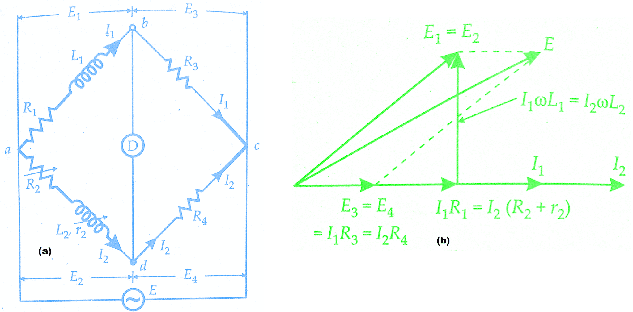
Let
L1 = unknown inductance of resistance R1
L2 = variable inductance of fixed resistance r2
R2 = variable resistance connected in series with inductor L2
R3,R4 = known non-inductive resistances
The theory of Maxwell’s Inductance Bridge has been explained already in ac bridges post.
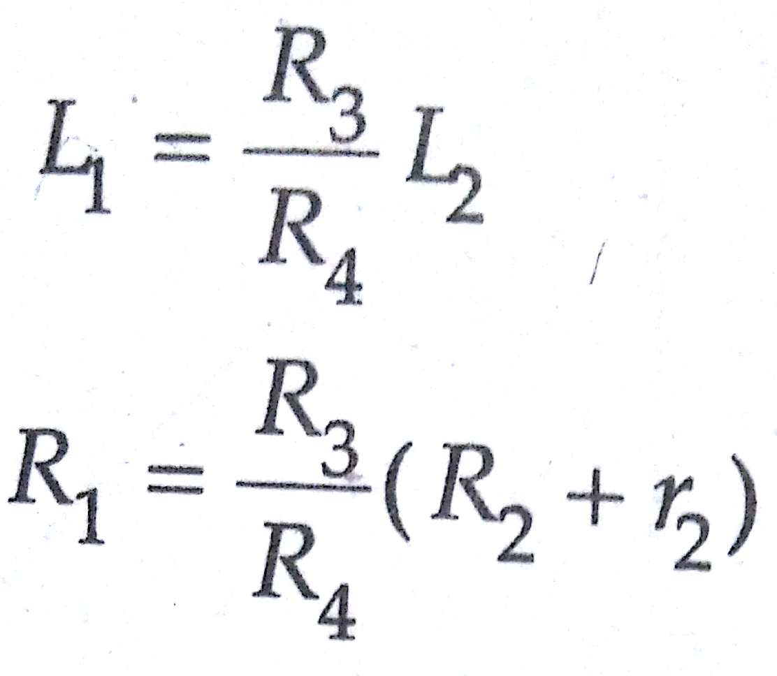
Resistors R3 and R4 are normally a selection of values from 10, 100, 1000 and 10,000 r2 is a decade resistance box. In some cases, an additional known resistance may have to be inserted in series with the unknown coil in order to obtain balance.
Measurement Of Self Inductance By Maxwell’s Inductance Capacitance Bridge:
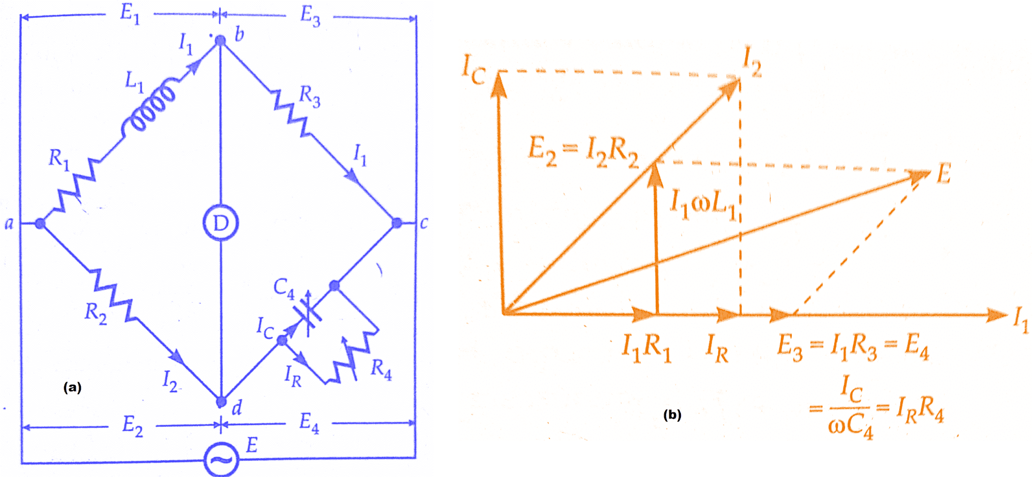
In Maxwell’s Inductance Capacitance Bridge, an inductance is measured by comparison. with a standard variable capacitance. The connections and the phasor diagram at the balance conditions are given in Maxwell’s Inductance Capacitance Bridge figure below.
Let L1 = unknown inductance,
R1 = effective resistance of inductor L1,
R2, R3, R4 = known non-inductive resistances,
and C4 = variable standard capacitor.
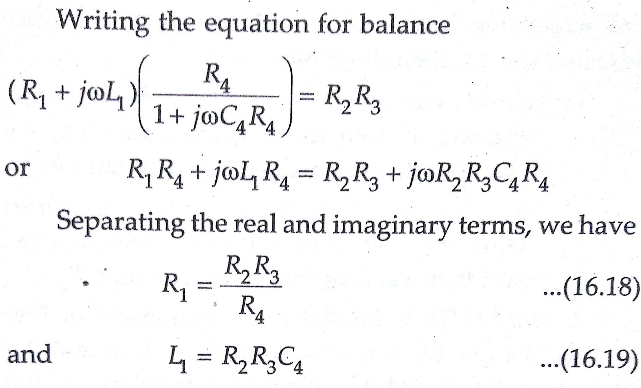
Thus we have two variables R4 and C4 which appear in one of the two balance equations and hence the two equations are independent.
The expression for Q factor,
Q = ωL₁/R₁ = ωC₄R₄
Advantages of Maxwell’s Inductance Capacitance Bridge:
The advantages of Maxwell’s Inductance Capacitance Bridge are
1.The two balance equations are independent if we choose R4 and C 4 as variable elements.
2.The frequency does not appear in any of the two equations.
3.Maxwell’s Inductance Capacitance Bridge yields a simple expression for unknowns L1 and R1 in terms of known bridge elements.
Physically R2 and R3 are each, say, 10, 100,1000 or 10,000 Q and their value is selected to give suitable value of product R2R3 which appears in both the balance equations; C4 is decade capacitor and R4 a decade resistor.
The simplicity of the bridge can be appreciated by the following example. Suppose the product R2R3 is 10⁶.Therefore, inductance is L1= C4 x 10⁶. Thus when the balance is achieved the value of C4 in μF directly gives the value of inductance in H.
4.The Maxwell’s inductance capacitance bridge is very useful for measurement of a wide range of inductance at the power and audio frequencies.
Disadvantages of Maxwell’s Inductance Capacitance Bridge:
The main disadvantages of Maxwell’s inductance capacitance bridge are
1.Maxwell’s Inductance Capacitance Bridge requires a variable standard capacitor which may be very expensive if calibrated to a high degree of accuracy. Therefore sometimes a fixed standard capacitor is used, either because a variable capacitor is not available or because fixed capacitors have a higher degree of accuracy and are less expensive than the variable ones. The balance adjustments are then done by
(a) either varying R2 and R4 and since R2 appears in both the balance equations, the balance adjustments become difficult
(b) putting an additional resistance in series with the inductance under measurement and then varying this resistance and R4.
2.The bridge is limited to measurement of low Q coils, (1 < Q < 10). It is clear that the measurement of high Q coils demands a large value for resistance R4, perhaps 10⁵ or 10⁶. The resistance boxes of such high values are very expensive. Thus for values of Q > 10, Maxwell’s bridge is unsuitable.
The Maxwell’s bridge is also unsuited for coils with a very low value of Q (i.e., Q < 1). Q values of this magnitude occur in inductive resistors, or in an R.F. coil if measured at low frequencies. The difficulty in measurement occurs on account of labour involved in obtaining balance since nominally a fixed capacitor is used and balance is obtained by manipulating resistances R2 and R4 alternately.This difficulty is explained as below:
A preliminary inductive balance is made with R2 and then R4 is varied to give a resistive balance which is dependent on the R2 setting. Accordingly, when R2 is changed for a second inductive balance, the resistive balance is disturbed and moves to a new value giving slow “convergence” to balance. This is particularly true of a low Q coil, for which resistance is prominent (as = wL/ R).
Thus a sliding balance condition prevails and it takes many manipulations to achieve balance for low Q coils with Maxwell’s bridge. From the above discussions, we conclude that Maxwell’s bridge is suited for measurements of only medium Q coils.
Conclusion:
In this, we have learnt Measurement Of Self Inductance By Maxwell’s Inductance & Maxwell’s Capacitance Bridge. You can download this article as pdf, ppt.
Comment below for any Queries.