Testing of Transformers:
Testing of transformers should be done to know the performance and characteristics of it.Initially manufacturers do the series testing of transformers before packing.
Transformers are very important and costly apparatus in power systems.Great care has to be exercised to see that the transformers are not damaged due to transient overvoltages of either lightning or power frequency.Hence, overvoltage tests become very important in the testing of transformers.Here, only the overvoltage tests are discussed, and other routine tests like the temperature rise tests, short circuit tests, etc. are not included and can be found in the relevant specifications.
(a) Induced Overvoltage Test:
Transformers are tested for overvoltages by exciting the secondary of the transformer from a high frequency a.c. source (100 to 400 Hz) to about twice the rated voltage.This reduces the core saturation and also limits the charging current necessary in large power transformers.The insulation withstand strength can also be checked.
(b) Partial Discharge Test:
Partial discharge tests on the windings are done to assess the discharge magnitudes and the radio interference levels . The transformer is connected in a manner similar to any other equipment and the discharge measurements are made. The location of the fault or void is sometimes done by using the travelling wave technique similar to that for cables. So far, no method has been standardized as to where the discharge is to be measured.Multi-terminal partial discharge measurements are recommended.Under the application of power frequency voltage, the discharge magnitudes greater than 104 pico coulomb are considered to be severe, and the transformer insulation should be such that the discharge magnitude will be far below this value.
Impulse Test of Transformer:
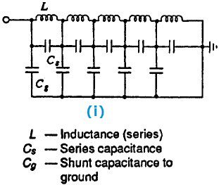 The purpose of the impulse tests is to determine the ability of the insulation of the transformers to withstand the transient voltages due to lightning, etc. Since the transients are impulses of short rise time, the voltage distribution along the transformer winding will not be uniform.The equivalent circuit of a transformer winding for impulses is shown in figure(i). If an impulse wave is applied to such a network (shown in figure(i)) the voltage distribution along the element will be uneven, and oscillations will be set in producing voltages much higher than the applied voltage.
Impulse testing of transformers is done using both the full wave and the chopped wave of the standard impulse, produced by a rod gap with a chopping time of 3 to 6 µs.To prevent large overvoltages being induced in the windings not under test, they are short circuited and connected to ground. But the short circuiting reduces the impedance of the transformer and hence poses problems in adjusting the standard waveshape of the impulse generators. It also reduces the sensitivity of detection.
(a) Procedure for Impulse Testing of transformers:
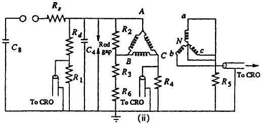
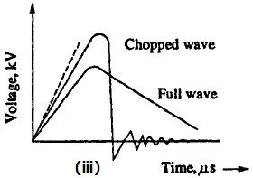
The schematic diagram for impulse testing of transformer is shown in figure (ii) and the wave shapes of the full and chopped waves are shown in figure (iii).In transformer testing it is essential to record the waveforms of the applied voltage and current through the windings under test.Sometimes, the transferred voltage in the secondary and the neutral current are also recorded.
Impulse testing of transformers is done in the following sequence:
(1) applying impulse voltage of magnitude 75% of the Basic Impulse Level (BIL) of the transformer under test,
 (2) one full wave voltage of 100% BIL,
(3) two chopped waves of 100% BIL,
(4) one full wave of 100% BIL, and
(5) one full wave of 75% BIL.
It is very important to see that the grounding is proper and the windings not under test are suitably terminated.
(b) Detection and Location of Fault During Impulse Testing:
The fault in a transformer insulation is located in impulse tests by any one of the
following methods.
General observations: The fault can be located by general observations like noise in the tank or smoke or bubbles in breather.
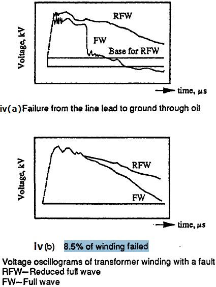 Voltage oscillogram method : Fault or failure appears as a partial or complete collapse of the applied voltage wave.Figure (iv) gives the typical waveform.The sensitivity of this method is low and does not detect faults which occur on less than 5% of the winding.
Neutral current method : In the neutral current method, a record of the impulse current flowing through a resistive shunt between the neutral and ground point is used for detecting the fault.The neutral current oscillogram consists of a high frequency oscillation, a low frequency disturbance, and a current rise due to reflections from the ground end of the windings. When a fault occurs such as arcing between the turns or from turn to the ground, a train of high frequency pulses similar to that in the front of the impulse current wave are observed in the oscillogram and the waveshape changes.If the fault is local, like a partial discharge, only high frequency oscillations are observed without a change of waveshape. The sensitivity of the method decreases, if other windings not under test are grounded.
Transferred surge current method: In this method, the voltage across a resistive shunt connected between the low voltage winding and the ground is used for fault location.A short high frequency discharge oscillation is capacitively transferred at the event of failure and is recorded.Hence, faults at a further distance from the neutral are also clearly located.The waveshape is distorted depending on the location and type of fault, and hence can be more clearly detected.
After the location of the fault, the type of fault can be observed by dismantling the winding and looking for charred insulation or melted parts on the copper winding.This is successful in the case of major faults.Local faults or partial discharges are self healing and escape observation.In this only impulse test of transformer is discussed and others routine tests like the temperature rise tests, short circuit tests, etc. are not discussed as they are mentioned in the specifications.
Does not Impulse test a destructuve test?
Thank you for your comment and for asking about the nature of an impulse test. Impulse testing is a type of testing that is used to evaluate the structural integrity of a material or component. It involves subjecting the material or component to a high-energy impact or shock load, which simulates the effects of an actual impact or shock that the material or component might experience in service.
In some cases, impulse testing can be a destructive test, meaning that the material or component is damaged or destroyed as a result of the test. However, not all impulse tests are destructive. It depends on the specific test setup and the type of material or component being tested. Some impulse tests are designed to be non-destructive, meaning that the material or component is not damaged or destroyed during the test. Instead, the test is used to measure the response of the material or component to the applied load, such as its deformation or displacement.
I hope this helps to clarify the nature of impulse testing. If you have any further questions or comments, please don’t hesitate to ask.
Thanks for sharing this useful piece of article on transformer testing and its types. It seems that people generally opt for impulse testing as it seems to be more efficient and accurate to obtain best results.
Power transformers in India | Transformer manufacturer in India