Induction Relays:
The induction type relays are also called magnitude relays. These relays work on the principle of the induction motor or an energy meter. In these relays, a metallic disc is allowed to rotate between the two electromagnets. The coils of the electromagnets are energised with the help of alternating currents.
The torque is produced in Induction relays due to the interaction of one alternating flux with eddy currents induced in the rotor by another alternating flux. The two fluxes have the same frequency but are displaced in time and space. As the interaction of alternating fluxes is the base of operation of Induction relays, these are not used for the d.c quantities. These are widely used for protective relaying involving only a.c quantities.

Types of Induction Relays:
Based on the construction, the various types of induction relays are:
1)Shaded pole Relays
2)Watt-hour meter Relays
3)Induction cup Relays
Before studying these types in detail, let us derive the torque equation for the induction type relays, which is same for all the three types of induction relays.
Must Read:
Torque Equation for Induction Type Relays:
As mentioned earlier, the alternating currents supplied to two electromagnets produce the two alternating fluxes φ1 and φ2.These two fluxes have the same frequency but they have a phase difference of α in between them such that φ2 leads φ1.Thus the two fluxes can be mathematically expressed as,
φ1 = φ1m sin ωt
φ2 = φ2m sin (ωt+α)
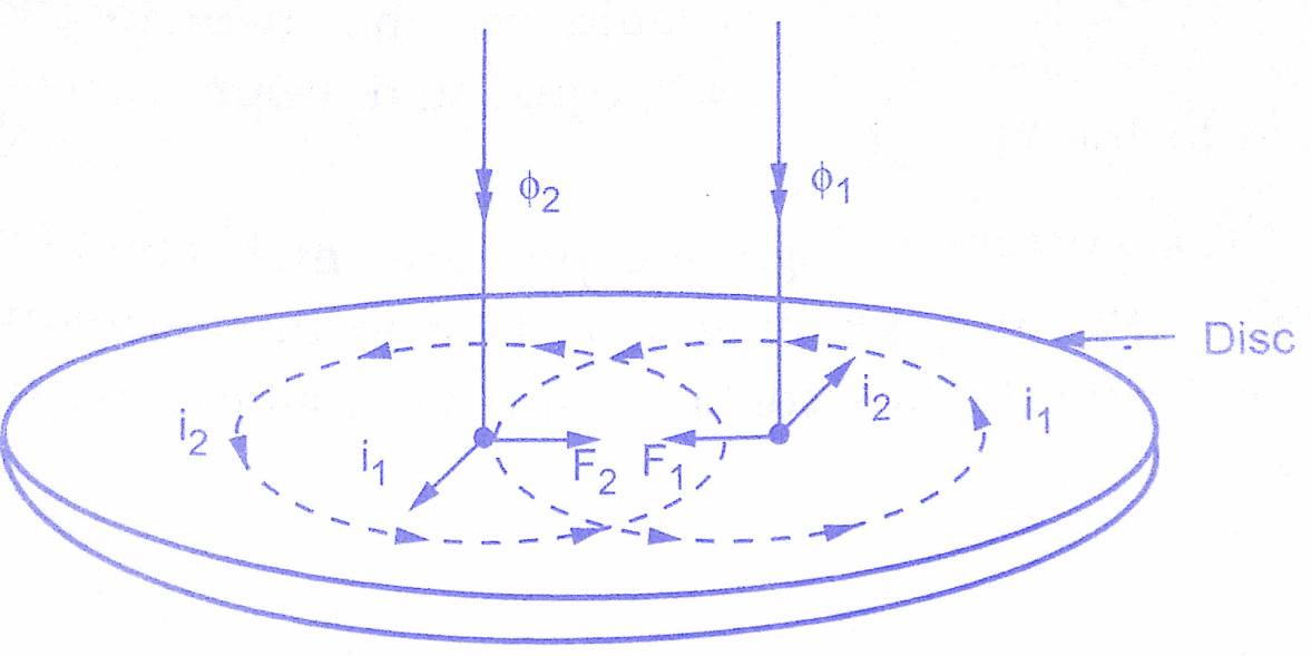
These alternating fluxes cause the induced e.m.f’s in the rotor. Due to the induced e.m.f.s, the eddy currents i1 and i2 are circulated in the disc. The two eddy currents react with each other to produce a force which acts on the rotor.
The figure above shows how the forces are produced in a section of the rotor due to the alternating fluxes.The instant considered to show the various quantities is when both the fluxes are directed downwards and are increasing in magnitude.The induced eddy currents lag behind the respective fluxes by 90⁰.
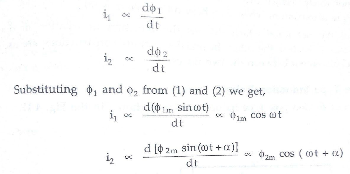
Assumption: The parts of the rotor in which rotor currents flow have negligible self-inductance and hence the rotor currents are in phase with the respective induced voltages. The induced voltages are proportional to the rate of change of fluxes and hence the eddy currents also are proportional to the rate of change of fluxes. Hence we can write,
The forces are produced due to the interaction of φ1 with i2 and φ2 with i1.
∴ F1 ∝ φ1 i2
and F2 ∝ φ2 i1
The directions of F1 and F2 can be obtained by Flemings left-hand rule. It can be seen from the above figure that the two forces are acting in the opposite directions and hence the net force acting on the disc is proportional to the difference between the two forces.
∴ F ∝ F2 – F1
∴ F ∝ φ2 i1 – φ1 i2
Substituting the proportional expressions of φ1, φ2, i1, i2 in the above equation we get,
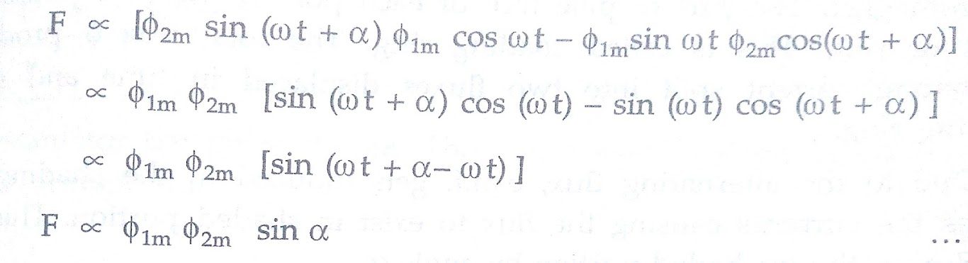
The equation above gives the net force acting on the disc which is proportional to sin ∝.
Substituting the r.m.s values of the fluxes instead of maximum values we get,
F ∝ φ1 φ2 sin ∝
It is important to note that the net force or torque acting on the disc is same at every instant. The action of Induction relay under such force is free from vibrations.
It can be observed from the above equation that if ∝ is zero then the net force is zero and disc cannot rotate.Hence there must exist a phase difference between the two fluxes.The torque is maximum when the phase difference ∝ is 90°.
The direction of the net force which decides the direction of rotation of disc depends on which flux is leading the other.In practice, various constructions are used to produce phase displacement between the two fluxes.
Shaded Pole Type Induction Relay:
The construction of Shaded Pole Type Induction Relay is shown in below figure.
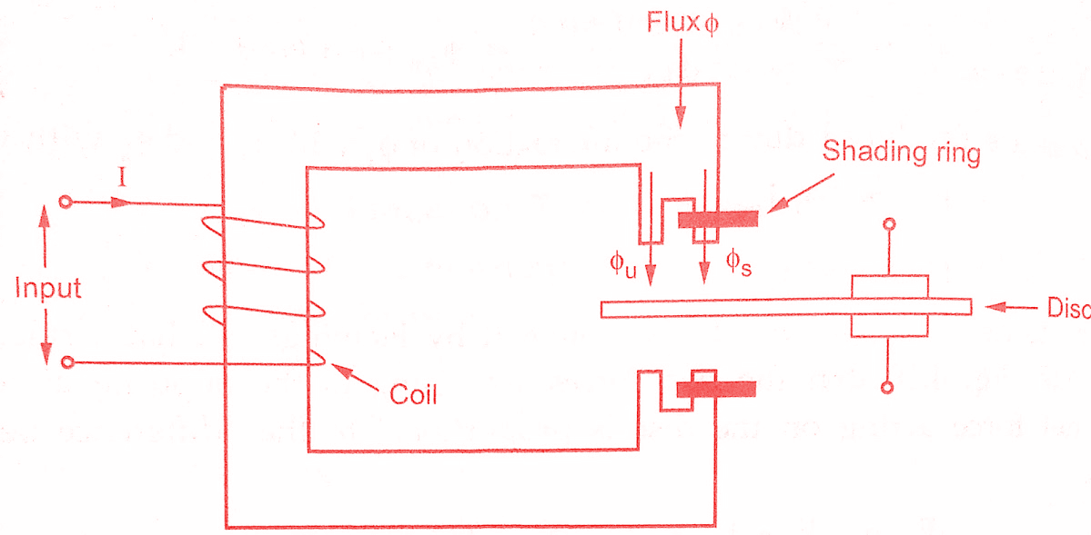
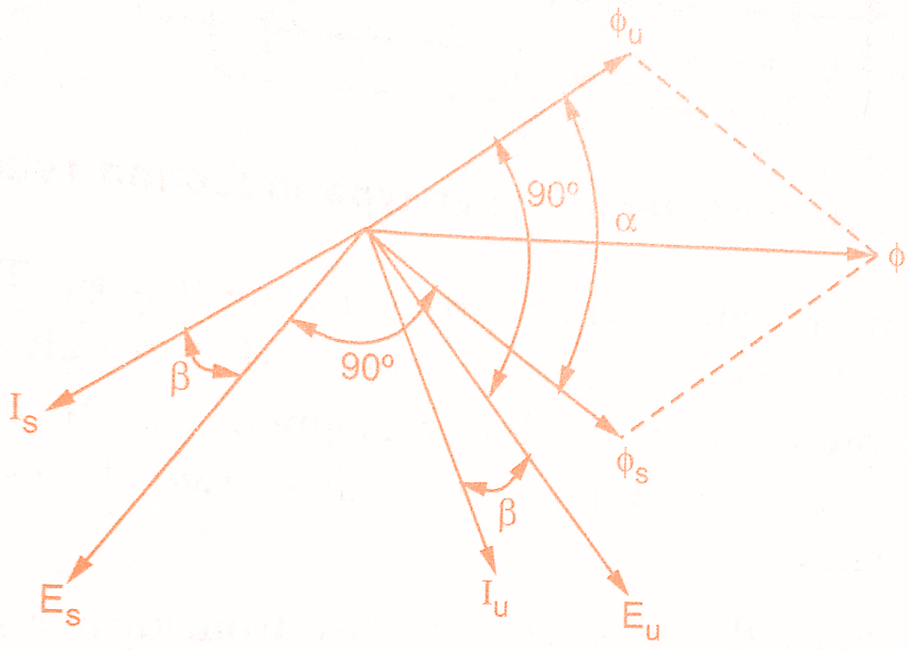
It consists of an aluminium disc which is free to rotate in an air gap of an electromagnet.The part of pole face of each pole is shaded with the help of copper band or ring.This is called shading ring.The total flux φ produced due to the alternating current split into two fluxes displaced in time and space due to the shading ring.
Due to the alternating flux, e.m.f gets induced in the shading ring.This e.m.f drives the currents causing the flux to exist in shaded portion.This flux lags behind the flux in the unshaded portion by angle ∝.
Let φs = Flux in shaded portion
φu = Flux in unshaded portion
Es = E.M.F. induced in the disc due to φs
Eu = E.M.F. induced in the disc due to φu
Is = Induced current due to Es
Iu = Induced current due to Eu
Eu lags behind φu by 90° while Es lags behind φs by 90°.The current Is lags Es by small angle β while Iu lags Eu by small angle β.This angle is generally neglected and Is and Iu are assumed to be in phase with Es and Eu respectively, in practice.The phasor diagram is shown in the figure below.
As proved in the previous section, neglecting It we get,
T ∝ φs φu sin ∝ (where T = Torque )
Assuming fluxes φs and φu to be proportional to the current I in the relay coil we can write,
T ∝ I² sin ∝
∴ T = kI² ( k = Constant )
As sin ∝ is constant for the given design.Thus the torque is proportional to the Aare of the current through the coil.
Watthour Meter Type Induction Relay:
The construction of Watthour Meter Type Induction relay is similar to the watthour meter which is very popularly used everywhere.Thus relay has double winding structure.The arrangement is shown in the figure below.
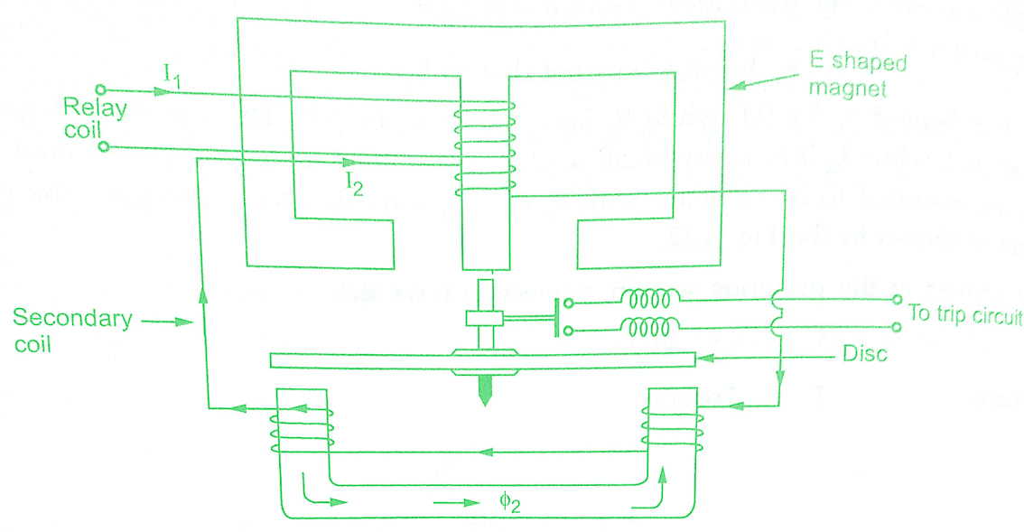
It consists of two magnets, one E shaped magnet and other U shaped magnet. The disc is free to rotate in between these two magnets. The upper E shaped magnet carries both primary winding which is relay coil and the secondary winding. The primary carries the relay current I1 which produces the flux φ1.The e.m.f gets induced in the secondary due to this flux. This drives current I2 through secondary.
Due to this current I2, flux φ2 gets produced in the lower magnet.This flux lags behind the main flux φ1 by an angle ∝.Due to the interaction of these two fluxes, the torque is exerted on the disc and disc rotates.
Assuming that the entire flux φ1 enters the disc from upper magnet and entire flux φ2 enters the disc from lower magnet, we can write,
T ∝ φ1 φ2 sin ∝
In Watthour Meter Type Induction relay, the tapping can be provided on the primary. With the help of this suitable number of primary turns can be selected and hence current setting can be adjusted. Most of the induction relays are of this type.
An important feature of Watthour Meter Type Induction relay is that its operation can be controlled by opening or closing of the secondary winding.It is opened, no current can flow through secondary hence flux φ2 cannot be produced and hence no torque can be produced.Thus relay can be made inoperative opening the secondary winding.
Induction Cup Relay:
The construction of induction cup relay is very similar to an induction motor as shown in below figure.
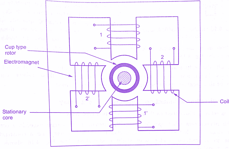
The stator consists of two, four or more poles. These are energized by the relay coils. The figure below shows 4 pole structure and the two pairs of coils. The coils 1 and 1′ are connected while the coils 2 and 2′ are connected to form two pairs of coils. The rotor is hollow cylindrical cup type in structure. Compared to induction motor the difference is that in induction cup relay the rotor core is stationary and only rotor conductor portion is free to rotate about its axis.
The currents and respective fluxes produced by the two pairs of coils are displaced from each other by angle ∝. Thus the resultant flux in the air gap is rotating.So rotating magnetic field is produced by two pairs of coils. Due to this, eddy currents are induced in the cup type rotor.
These currents produce the flux. The interaction of the two fluxes produce the torque and the rotor rotates in the same direction as that of rotating magnetic field. A control spring and the back stop carried on an arm attached to the spindle of the cup, are responsible to prevent continuous rotation
Induction cup relay is very fast in operation. The operating time of the order of 10 milliseconds is possible with this type. This is because the rotor is light having very low moment of (induction loop) inertia. The induction cup structure can be used for two quantity or single quantity relays.
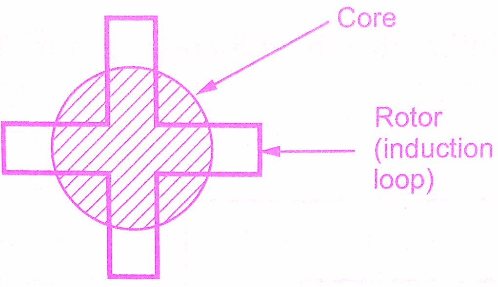
A single quantity relay means both the coils are fed by the same actuating quantity with a fixed phase angle shift in between them. To reduce the rotor inertia and to make the operation faster, double induction loop structure is used.Such a structure is shown in the above figure.
In all, the induction relays are widely used for protective relays involving a.c quantities. High, low and adjustable speeds are possible in these relays. Various shapes of time against operating quantity curves can be obtained.
Conclusion :
We have learnt Working Principle, Construction & Types of Induction Type Relays.You can download this article as pdf, ppt.
Comment below for any Queries.
Great understanding explanation.. Thank you!
Thank you for taking the time to read the blog and leaving your positive feedback! It’s great to hear that the explanation was helpful to you.
Very good concept