Non-directional Induction Overcurrent Relay:
This relay is also called earth leakage induction type relay. The overcurrent relay operates when the current in the circuit exceeds a certain preset value. The induction type nondirectional overcurrent relay has a construction similar to a watthour meter, with slight modification. The figure below shows the constructional of nondirectional induction type overcurrent relay. It consists of two electromagnets.
The upper is E shaped while the lower is U shaped. The aluminium disc is free to rotate between the two magnets. The spindle of the disc carries moving contacts and when the disc rotates the moving contacts come in contact with fixed contacts which are the terminals of a trip circuit. The upper magnet has two windings, primary and secondary.
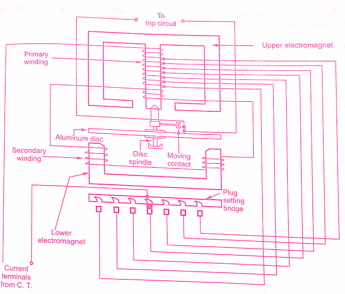
The primary is connected to the secondary of C.T on the line to be protected. This winding is tapped at intervals. The tappings are connected to plug setting bridge. With the help of this bridge, the number of turns of the primary winding can be adjusted. Thus the desired current setting for the Non-Indirectional Induction Overcurrent Relay can be obtained. There are usually seven sections of tappings to have the overcurrent range from 50% to 200% in steps of 25%.
Must Read:
- Induction Type Relays Working Principle, Construction and Types
- Electromagnetic Attraction Relays – Working ,Construction & Types
These values are percentages of the current rating of the relay.Thus a relay current rating may be 10 A i.e. it can be connected to C.T. with the secondary current rating of 10 A but with 50 % setting the relay will start operating at 5A.
So adjustment of the current setting is made by inserting a pin between spring loaded jaw of the bridge socket, at the proper tap value required. When the pin is withdrawn for the purpose of changing the setting while Non-Indirectional Induction Overcurrent Relay is in service then relay automatically adopts a higher current setting thus secondary of C.T. is not open circuited.
So relay remains operative for the fault occurring during the process of changing the setting. The secondary winding on the central limb of upper magnet is connected in series with winding on the lower magnet. This winding is energized by the induction from the primary. By this arrangement of secondary winding, the leakage fluxes of upper and lower magnets are sufficiently displaced in space and time to produce a rotational torque on the aluminium disc.
The control torque is provided by the spiral spring. When current exceeds its preset value, the disc rotates and moving contacts on spindle make the connection with trip circuit terminals. The angle through which the disc rotates is between 0° to 360°. The travel of the moving contacts can be adjusted by adjusting the angle of rotation of the disc.
This gives the Non-Indirectional Induction Overcurrent Relay any desired time setting which is indicated by a pointer on a time setting dial. The dial is calibrated from 0 to 1. This does not give direct operating time but it gives multiplier which can be used along with the time-plug setting multiplier curve to obtain the actual operating time of the relay.The time-plug setting multiplier curve is provided by the manufacturer.
Time-Current Characteristics of Non-Indirectional Induction Overcurrent Relay:
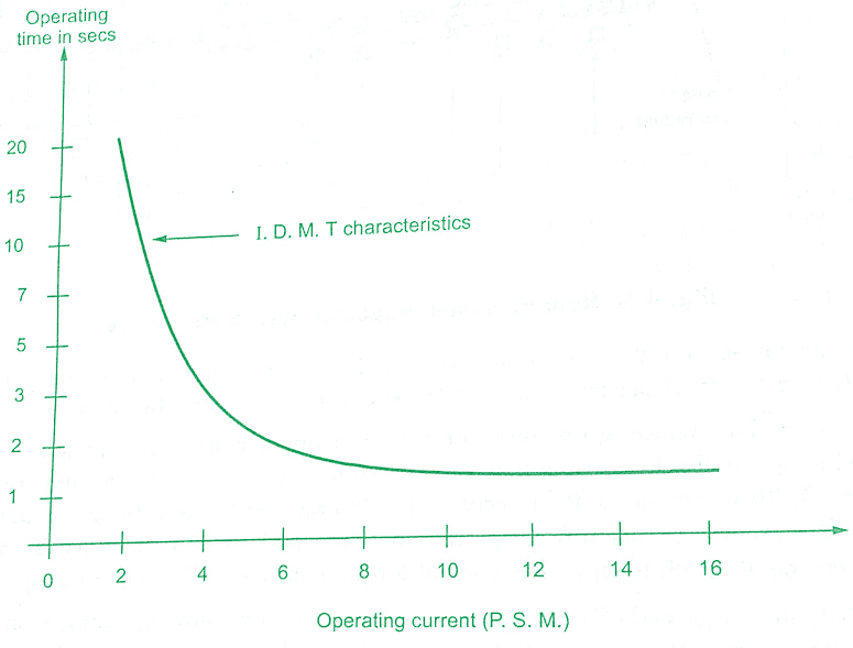
The time required to rotate the disc depends on a torque. The torque varies as current in the primary circuit. More the torque, lesser is the time required hence Non-Indirectional Overcurrent relay has inverse time characteristics. The figure below shows the time-current characteristics for the Non-Indirectional overcurrent relay. Such characteristics are called Inverse Definite Minimum Type (I.D.M.T.) characteristics.
This is because the characteristics show the inverse relation between time and current for small values of currents. But as current increases, some definite time is required by the relay. So the characteristics becomes straight line for higher values of currents. Such IDMT characteristics can be obtained by saturating the iron in the upper magnet so that there cannot be increase in the flux once current achieves certain high value.
The P.S.M can be obtained,

Fault current in relay coil = Line fault current × C.T Ratio
Non-Indirectional Induction Type Overcurrent Relay Working:
The torque is produced due to induction principle, as explained in Non Indirectional Induction Type Overcurrent Relay. This torque is opposed by restraining force produced by spiral springs. Under normal conditions, the restraining force is more than driving force hence disc remains stationary.
Under fault conditions when the current becomes high, the disc rotates through the preset angle and makes contact with the fixed contacts of the trip circuit. The trip circuit opens the circuit breaker, isolating the faulty part from rest of the healthy system.
Must Read:
Calculation of Relay Operating Time:
Practically, it is necessary to calculate the actual operating time of the relay, under the specific fault current levels. For these calculations, the following parameters related to the Non-Indirectional Induction Overcurrent Relay must be known.
1. Time/P.S.M. curve or tabular data.
2. Current setting.
3. Time setting multiplier.
4. Level of fault current.
5. Corresponding C.T. ratio.
This Non-Indirectional Induction Overcurrent Relay operating time can be obtained as,
1. Using the C.T ratio, convert the fault current level to relay coil current level.
2.Calculate the plug setting multiplier from the relay coil current and current setting.
3. From the Time/P.S.M curve on data, obtain the time corresponding to the plug setting multiplier calculated above.
4. Multiplying the time obtained by time multiplier setting, the actual relay time can be obtained.
Conclusion:
Today we have learnt about Working Principle, Construction of Non-Indirectional Induction Type Overcurrent Relay.You can download this article as pdf, ppt.
Comment below for any Queries.
Thanks for sharing the amazing content. I will also share with my friends. Great content thanks a lot.
Thank you for your kind words and for sharing the blog with your friends! I’m glad that you found the content useful and interesting.