Rotating Magnetic Field (RMF) in Synchronous Machines:
As we know synchronous machines can be operated by rotating either armature or magnetic field but practically most of the alternators and motors prefer rotating field type and keeping armature stationary due to certain advantages.
1.The rotating magnetic field (RMF) is very important to understand the working of the synchronous motor.
2.The rotating magnetic field can be defined as the field or flux having constant amplitude but whose axis rotates in a plane at a certain speed e.g. permanent magnet rotating in a space produces a rotating magnetic field.
3.Similarly, if an arrangement is made to rotate the poles, with constant excitation supplied, the resulting field is rotating magnetic field.
4.So a field produced in an air gap of a rotating field type alternator is of rotating type.But this is all about the production of R.M.F by physically rotating poles or magnet.
5.In practice, such a rotating magnetic field can be produced by exciting a set of stationary coils or windings with the help of polyphase a.c supply.
6.The resultant flux produced in such a case has constant magnitude and its axis rotates in space without physically rotating the windings.Let us study how it happens.
Must Read:
Production of Rotating Magnetic Field in Synchronous Machines:
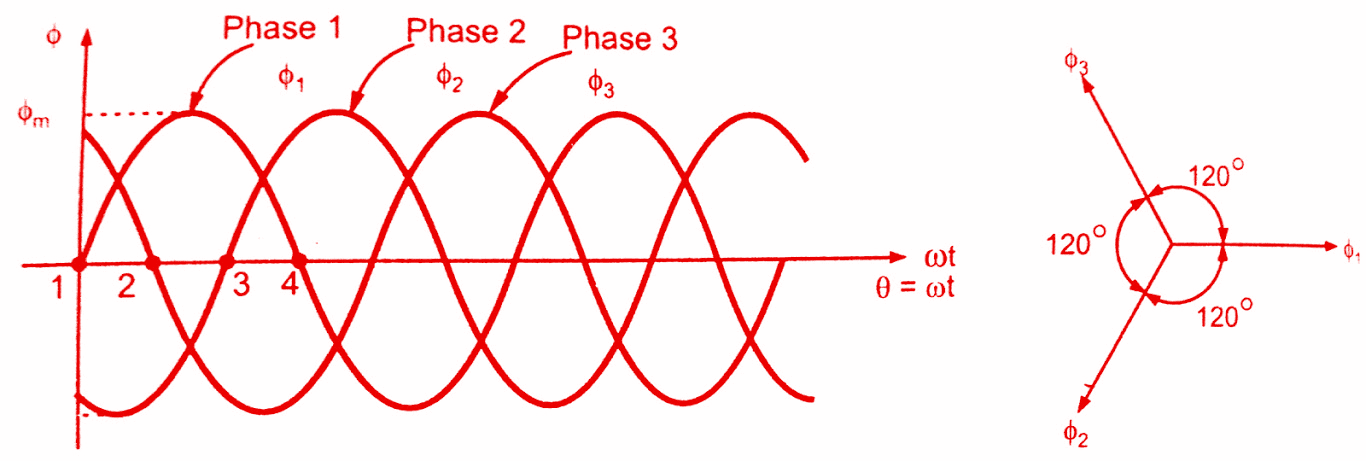
Consider a three phase windings displaced in space by 120°, supplied by a three phase a.c supply.The three phase currents are also displaced from each other by 120°.The flux produced by each phase current is also sinusoidal in nature and all three fluxes are separated from each other by 120°. If the phase sequence of the windings is 1-2-3, then the mathematical equation for the instantaneous values of the fluxes Φ1, Φ2 and Φ3 can be given as,
Φ1 = Φm Sin (wt ) = Φm sin θ
Φ2 = Φm Sin (wt – 120°) = Φm sin (θ-120°)
Φ3 = Φm Sin (wt – 240°) = Φm sin (θ-240°)
As windings are identical and supply is balanced the amplitude of each flux is same i.e. Φm.The waveforms of three fluxes are shown in figure(a) below while the assumed positive directions of these fluxes in space are shown in figure(b).Assumed positive, direction means whenever the instantaneous value of flux is positive, in the vector diagram, it must he represented along its assumed positive direction.And if flux has negative instantaneous value then must be represented in opposite direction to the assumed positive direction, in the vector diagram of rotating magnetic field.
Let Φ1, Φ2 and Φ3 be the instantaneous values of the fluxes.The resultant flux ΦT at any instant is given by phasor combination of Φ1, Φ2 and Φ3 at that instant.Let us find out ΦT at four different instants 1, 2, 3 and 4 as shown in figure(a) above i.e. respectively at θ = 60°, 120° and 180°.
Case i) θ = 0°
Substituting in equations (1), (2) and (3) we get,
Φ1 = Φm Sin 0° = 0
Φ2 = Φm sin (-120°) = – 0.866 Φm
Φ3 = Φm Sin ( – 240°) = +0.866 Φm
And ΦT = Φ1 + Φ2 + Φ3
Show positive values in assumed positive directions and negative in opposite directions to assumed positive directions.Hence diagram looks like as shown in figure(a) below.
BD is perpendicular drawn from B on ‘ΦT‘ .
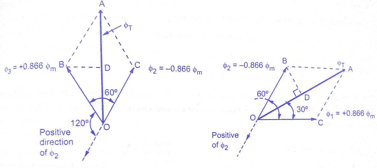
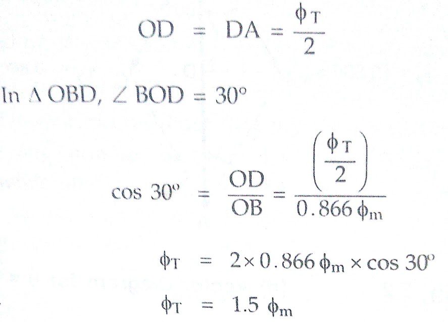
So the magnitude of resultant flux is 1.5 times the maximum value of an individual flux.
Case ii) θ = 60°
Substituting in equations (1), (2) and (3) we get,
Φ1 = Φm Sin 60° = +0.866 Φm
Φ2 = Φm sin (-60°) = – 0.866 Φm
Φ3 = Φm Sin ( – 180°) = 0
So Φ1 is positive and Φ2 is negative so vector diagram looks like as shown in figure(b) above.
It can be seen from figure(b), that,
ΦT = 1.5 Φm
So the magnitude of the resultant is same as before but it is rotated in space by 60° in clockwise direction, from its previous position.
Case iii) θ = 120°
Substituting in equations (1), (2) and (3), we get,
Φ1 = Φm Sin 120° = +0.866 Φm
Φ2 = Φm sin (0°) = 0
Φ3 = Φm Sin ( – 120°) = – 0.866 Φm
So Φ1 is positive, Φ2 is zero and Φ3 is negative.So vector diagram looks like as shown in figure(c). From figure(c), it can be proved easily that,
ΦT = 1.5 Φm
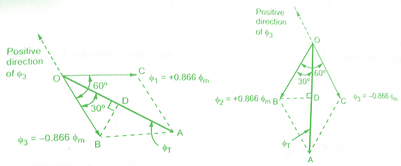
So the magnitude of the resultant is once again 1.5 Φm, same as before.While it is further rotated in space by 60° from its previous position at θ = 60°.
Case iv) θ = 180°
Substituting in equations (1), (2) and (3) we get,
Φ1 = Φm Sin 180° = 0
Φ2 = Φm sin (60°) = +0.866 Φm
Φ3 = Φm Sin ( – 68°) = – 0.866 Φm
So Φ1 is zero, Φ2 is positive and Φ3 is negative. The vector diagram is as shown in figure(d) below. From the vector diagram, it can be proved that,
ΦT = 1.5 Φm
So the magnitude of resultant flux is once again 1.5 Φm but it is further rotated by 60° in a clockwise direction from its position for θ = 120°.
So for a half cycle of the fluxes, the resultant has rotated through 180°. This is applicable for 2 pole winding.From this discussion we can have following conclusions:
a) The resultant of the three alternating fluxes, separated from each other by 120°, has a constant amplitude of 1.5 Φm, where Φm is the maximum amplitude of an individual flux due to any phase.
b) The resultant always keeps on rotating with a certain speed in space.
This is nothing but satisfying the definition of a rotating magnetic field. Hence we can include that the three phase stationary winding when connected to a three phase a.c. apply produces a rotating magnetic field. The speed of the resultant is 180° in space, for 180° electrical of the fluxes for a 2 pole ending as discussed above.
Key Point: This is nothing but,
°mechanical = °electrical for 2 pole case.
If the winding is wound for P poles, then resultant will complete 2/p revolutions for 360° electrical of the fluxes.The relation is exactly similar to what we have discussed earlier in case of the alternator.So resultant flux bears a fixed relation between the speed of rotation, supply frequency and the number of poles for which winding is wound.The relation is already derived while studying an alternator.So for a standard supply frequency of ‘f’ Hz of a three phase a.c. supply and ‘P’ poles of the three phase windings,the speed of the rotating magnetic field is Ns r.p.m.
Key Point: So for a rotating magnetic field,
Ns = 120.f/p r.p.m.
Must Read:
Direction of Rotating Magnetic Field:
The direction of the rotating magnetic field in Synchronous Machines is always from the axis of the leading phase of the three phase winding towards the lagging phase of the winding.In the example above the phase sequence is 1-2-3 i.e. phase 1 leads 2 by 120° and phase 2 leads 3 by 1200.So rotating magnetic field rotates from axis of 1 to axis of 2 and then to axis of 3 i.e. in the clockwise direction as seen above.
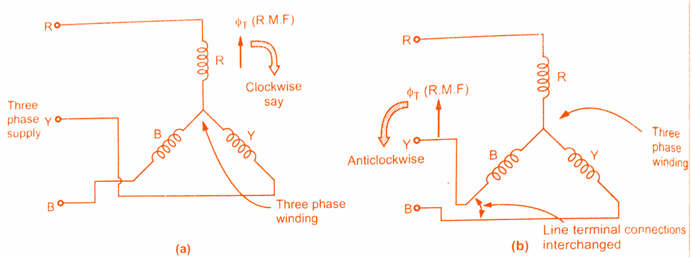
This direction can be reversed by changing any two terminals of three phase winding while connecting them to three phase supply.So in practice for a phase sequence of R-Y-B, the rotating magnetic field is rotating in clockwise direction, then by changing any two terminals of the winding it can be changed to anticlockwise, as shown in figure(a) and (b) below.
Conclusion:
Now here we have learnt about how rotating Magnetic field in Synchronous Machines is produced.You can download this article as pdf, ppt.
Comment below for any Queries.