Single phase Induction Motors:
Single-phase a.c supply is commonly used for lighting purpose in shops, offices, houses, schools etc..Hence instead of d.c motors, the motors which work on single-phase a.c. supply are popularly used. These a.c motors are called single-phase induction motors. A large no. of domestic applications use single-phase induction motors. Here we will learn how does single phase induction motor work.
The power rating of these motors is very small. Some of them are even fractional horsepower motors, which are used in applications like small toys, small fans, hairdryers etc. This article explains the construction, working principle of single-phase induction motors.
Construction of Single Phase Induction Motors:
Similar to a d.c motor, single-phase induction motor also has two main parts, one rotating and other stationary. The stationary part in single-phase induction motors is Stator and the rotating part is Rotor.
The stator has laminated construction, made up of stampings. The stampings are lotted on its periphery to carry the winding called stator winding or main winding. This is excited by a single-phase a.c supply. The laminated construction keeps iron losses to the minimum. The stampings are made up of material from silicon steel which minimises the hysteresis loss.
The stator winding is wound for a certain definite number of poles means when excited by single-phase a.c supply, stator produces the magnetic field which creates the effect of the certain definite number of poles. The number of poles for which stator winding is wound decides the synchronous speed of the motor. The synchronous speed is denoted as Ns and it has a fixed relation with supply frequency f and number of poles P. The relation is given by,
Ns = 120f/p RPM
This textbook “Electrical Machinery by P.S. Bhimbhra” is the best in industry. Grab it now for very less price.

Must Read:
- Construction & Working principle of Synchronous Motor
- Armature Windings in Alternator and Types of Armature Windings
The induction motor never rotates with the synchronous speed but rotates at a speed that is slightly less than the synchronous speed. The rotor construction is of squirrel cage type. This rotor consists of uninsulated copper or aluminium bars, placed in the slots.
The bars are permanently shorted at both the ends with the help of conducting rings called end rings. The entire structure looks like cage hence it is called a squirrel cage rotor. The construction of single-phase induction motors is shown in below figure:
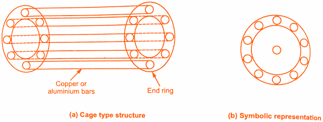
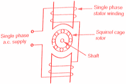
As the bars are permanently shorted to each other, the resistance of the entire rotor is very very small. The air gap between stator and rotor is kept uniform and as small as possible. The main feature of this rotor is that it automatically adjusts itself for the same the number of poles as that of the stator winding. The schematic diagram of two-pole single phase induction motor is shown in the below figure:
Working Principle of Single Phase Induction Motors:
For the motoring action, there must exist two fluxes which interact with each other to produce the torque. In d.c motors, field winding produces the main flux while d.c supply given to armature is responsible to produce armature flux. The main flux and armature flux interact to produce the torque.
In the single-phase induction motor, single-phase a.c supply is given to the stator winding. The stator winding carries an alternating current which produces the flux which is also alternating in nature. This flux is called the main flux. This flux links with the rotor conductors and due to transformer action e.m.f gets induced in the rotor. The induced emf drives current through the rotor as the rotor circuit is the closed circuit.
This rotor current produces another flux called rotor flux required for the motoring action. Thus second flux is produced according to the induction principle due to induced e.m.f hence the motor is called induction motor. As against this in d.c motor a separate supply is required to the armature to produce armature flux. This is an important difference between d.c motor and an induction motor.
Key Point: Another important difference between the two is that the d.c. motors are self-starting while single-phase induction motors are not self-starting. Let us see why single-phase induction motors are not self-starting with the help of a theory called double-revolving field theory.
This textbook “Electrical Machinery by P.S. Bhimbhra” is the best in industry. Grab it now for very less price.
Must Read:
Double Revolving Field Theory in single-phase induction motors:
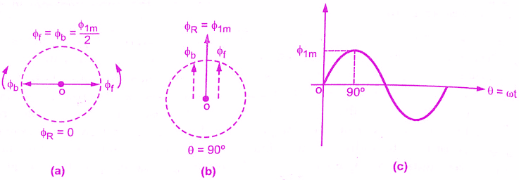
According to this theory, any alternating quantity can be resolved into two rotating components which rotate in opposite directions and each having magnitude as half of the maximum magnitude of the alternating quantity. In case of single-phase induction motors, the stator winding produces an alternating magnetic field having the maximum magnitude of Φ1m.
According to double-revolving field theory, consider the two components of the stator flux, each having magnitude half of maximum magnitude of stator flux i.e (Φ1m/2). Both these components are rotating in opposite directions at the synchronous speed Ns which is dependent on frequency and stator poles.
Let Φf is forward component rotating in anticlockwise direction while Φb is the backward component rotating in a clockwise direction. The resultant of these two components at any instant gives the instantaneous value of the stator flux at that instant. So resultant of these two is the original stator flux. The below figure shows the stator flux and its two components Φf and Φb .
At the start, both the components are shown the opposite to each other in figure(a). Thus the resultant ΦR = 0. This is nothing but the instantaneous value of stator flux at the start. After 90°, as shown in figure(b), the two components are rotated in such a way that both are pointing in the same direction.
Hence the resultant ΦR is the algebraic sum of the magnitudes of the two components. So ΦR = (Φ1m/2) + (Φ1m/2) =Φ1m.This is nothing but the instantaneous value of the stator flux at 0 = 90° as shown in figure(c). Thus continuous rotation of two components gives the original alternating stator flux.
Both the components are rotating and hence get cut by the rotor conductors. Due to the cutting of flux, e.m.f gets induced in the rotor which circulates the rotor current. The rotor current produces rotor flux. This flux interacts with forwarding component Φf to produce a torque in one particular direction say anticlockwise direction. While the rotor flux interacts with the backward component Φb to produce a torque in the clockwise direction. So if anticlockwise torque is positive then clockwise torque is negative.
At the start, these two torques are equal in magnitude but opposite in direction. Each torque tries to rotate the rotor in its own direction. Thus net torque experienced by the rotor is zero at the start. And hence the single-phase induction motors are not self-starting. By providing the additional flux, we can make the motor self starting. Some of the self starting single phase induction motors are Capacitor Start Induction Motor, Shaded pole induction motor, Permanent split capacitor motor.
Torque-Speed Characteristics in Single-phase Induction Motors:
The two oppositely directed torques and the resultant torque can be shown effectively with the help of torque-speed characteristics.
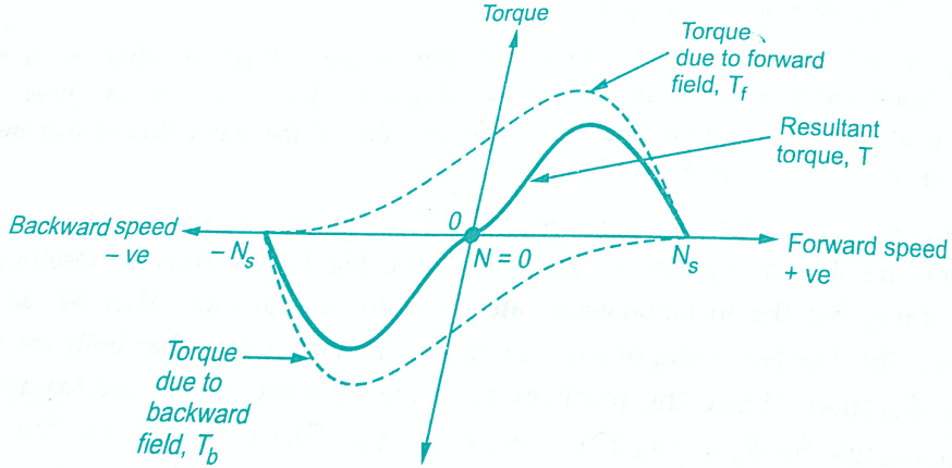
It can be seen that at start N = 0 and at that point resultant torque is zero. So single phase induction motors are not self starting. However if the rotor is given an initial rotation in any direction, the resultant average torque increases in the direction in which rotor is initially rotated and the motor starts rotating in that direction.
But in practice, it is not possible to give initial torque to rotor externally hence some modifications are done in the construction of single phase induction motors to make them self starting.Another theory which can also be used to explain why single phase induction motor is not self starting is cross-field theory.
Cross Field Theory in single phase induction motors:
Consider a single phase induction motor with standstill rotor as shown in the below figure.The stator winding is excited by the single phase a.c. supply.This supply produces an alternating flux Φs which acts along the axis of the stator winding.Due to this flux, emf gets induced in the rotor conductors due to transformer action.
As the rotor is closed one, this e.m.f circulates current through the rotor conductors.The direction of the rotor current is as shown in the below figure.The direction of rotor current is so as to oppose the cause producing it, which is stator flux Φs.
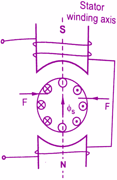
Now Fleming’s left hand rule can be used to find the direction of the force experienced by the rotor conductors.It can be seen that when Φs acts in upward direction and increasing positively, the conductors on left experience force from left to right while conductors on right experience force from right to left.Thus overall, the force experienced by the rotor is zero.Hence no torque exists on the rotor and rotor can not start rotating.
We have seen that there must exist two fluxes separated by some angle so as to produce rotating magnetic field.According to cross field theory, the stator flux can be resolved into two components which are mutually perpendicular.One acts along the axis of the stator winding and other acts perpendicular to it.
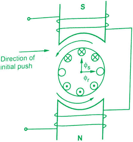
Assume now that an initial push is given to the rotor in an anticlockwise direction. Due to the rotation, rotor physically cuts the stator flux and dynamically emf gets induced in the rotor. This is called speed e.m.f or rotational emf. The direction of such emf can be obtained by Fleming’s right-hand rule and this emf is in phase with the stator flux Φs.
The direction of emf is shown in the figure below. This emf is denoted as E2N. This emf circulates current through rotor which is I2N. This current produces its own flux called rotor flux Φr. This axis of Φr is at 90° to the axis of stator flux hence this rotor flux it called cross-field.
This textbook “Electrical Machinery by P.S. Bhimbhra” is the best in industry. Grab it now for very less price.
Must Read:
Due to very high rotor reactance, the rotor current I2N and Φr lag the rotational emf by almost 90°. Thus Φr is in quadrature with Φs in space and lags Φs by 90° in time phase. Such two fluxes produce the rotating magnetic field.
The direction of this rotating magnetic field will be the same as the direction of the initial push given. Thus rotor experiences a torque in the same direction as that of rotating magnetic field i.e. the direction of the initial push. So rotor accelerates in the anticlockwise direction under the case considered and attains a subsynchronous speed in the steady state.
Conclusion:
Now today we have discussed Working Principle & Construction of Single phase Induction Motors. You can download this article as pdf, ppt.
Comment below for any Queries.
I want to download this article, but I don’t know how to download it as pdf
Hi Mohammed Firdaus, please click cntrl+P on your laptop and you can save it as PDF.
Very good post. I really like it. To read this type of Post In Hindi
Visit this Website.
https://hindi.electricaldiary.com/2020/05/single-phase-induction-motor.html