Lissajous Patterns of Cathode Ray Oscilloscope:
We have already discussed Cathode Ray Oscilloscope or CRO. It is a very important oscilloscope used to analyse the waveform and measure them. Now here we will discuss how the measurement of waveform i.e measurement of phase difference and frequency using CRO which are Lissajous patterns.
It is interesting to consider the characteristics of patterns that appear on the screen of a CRT when sinusoidal voltages are simultaneously applied to horizontal and vertical plates. These patterns are called ‘Lissajous Patterns’.
Phase measurement of Cathode Ray Oscilloscope:
When two sinusoidal voltages of equal frequency which are in phase with each other are applied to the horizontal and vertical deflection plates, the pattern appearing on the screen is a straight line as is clear from the below figure.
Must Read:
- Comparison Between Cathode ray and Digital Storage Oscilloscopes
- Digital Storage Oscilloscope(DSO) Working Principle and its Operation
- Electrical resistor | Materials used in precision Resistors
 |
| Lissajous pattern with equal frequency voltages and zero phase shift. |
|
| Lissajous pattern with equal frequency voltages and zero phase shift. |
Thus when two equal voltages of equal frequency but with 90° phase displacement are applied to a CRO, the trace on the screen is a circle. This is shown in the below figure.
When two equal voltages of equal frequency but with a phase shift (I) (not equal to 0° or 90°) are applied to a CRO we obtain an ellipse as shown in the below figure. An ellipse is also obtained when unequal voltages of the same frequency are applied to the CRO.
This textbook “Electrical and Electronics Measurements by S. Chand” is the best in industry. Grab it now for very less price.
A number of conclusions can be drawn from the above discussions. When two sinusoidal voltages of the same frequency are applied :
(i) A straight line results when the two voltages are equal and are either in phase with each other or 180° out of phase with each other. The angle formed with the horizontal is 45° when the magnitudes of voltages are equal. An increase in the vertical deflection voltage causes the line to have an angle greater than 45° with the horizontal. On the other hand, a greater horizontal voltage makes the angle less than 45° with the horizontal.
(ii) Two sinusoidal waveforms of the same frequency produce a Lissajous pattern, which may be a straight line, a circle or an ellipse depending upon the phase and magnitude of the voltages.
A circle can be formed only when the magnitude of the two signals are equal and the phase difference between them is either 90° or 270°. However, if the two voltages are not equal and/or out of phase an ellipse is formed. If the Y voltage is larger, an ellipse with vertical major axis is formed while if the X plate voltage has a greater magnitude, the major axis of the ellipse lies along the horizontal axis.
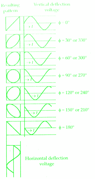
(ii)) It is clear from the below figure, that for equal voltages of same frequency progressive variation of phase voltage causes the pattern to vary from a straight diagonal line to ellipses of different eccentricities and then to a circle, after that through another series of ellipses and finally a diagonal straight line again.
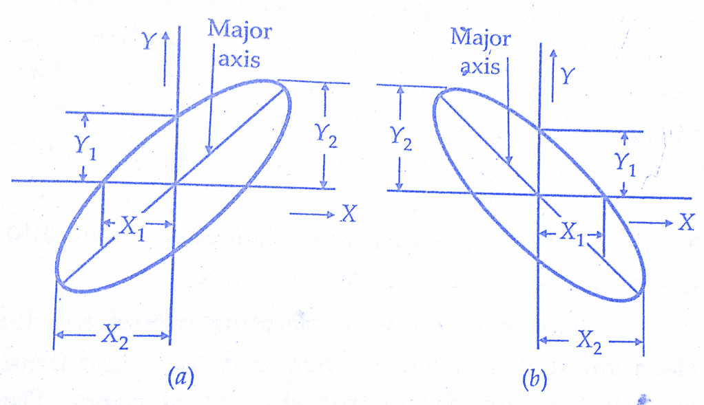
Regardless of the two amplitudes of the applied voltages, the ellipse provides a simple means of measuring phase difference between two voltages. Referring to figure, the sine of the phase angle between the voltages is given by :
![Measurement of Phase & Frequency [Lissajous Patterns] of CRO](https://www.electricalengineeringinfo.com/wp-content/uploads/2016/11/Lissajous2BPatterns-of-Cathode2Bray2Boscilloscope-cro-8.jpg)
For convenience, the gains of the vertical and horizontal amplifiers are adjusted so that the ellipse fits exactly into a square marked by the lines on the graticule.
If the major axis of the ellipse lies in the first and third quadrants (i.e., its slope is positive) as in the below figure(a) the phase angle is either between 00 to 90° or between 270° to 360°.When the major axis of ellipse lies in second and fourth quadrants i.e. when its slope is negative as in the figure(b), the phase angle is either between 90° and 180° or between 180° and 270°.
Frequency measurement of cro or cathode ray oscilloscope :
Lissajous patterns may be used for accurate measurement of frequency. The signal, whose frequency is to be measured, is applied to the Y plates. An accurately calibrated standard variable frequency source is used to supply voltage to the X plates, with the internal sweep generator switched off.
The standard frequency is the adjusted unit the pattern appears as a circle or an ellipse, indicating that both signals are of the same frequency. Where it is not possible to adjust the standard signal frequency to the exact frequency of the unknown signal, the standard if adjusted to multiple or a submultiple of the frequency of the unknown source so that the pattern appears stationary.
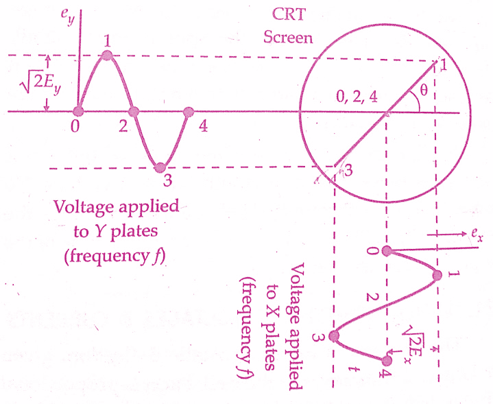
Let us consider an example.Suppose sine waves are applied to X and Y plates as shown in the figure below.Let the frequency of wave applied to Y plates is twice that of the voltage applied to X plates.This means that the CRT spot travels two complete cycles in the vertical direction against one in the horizontal direction.
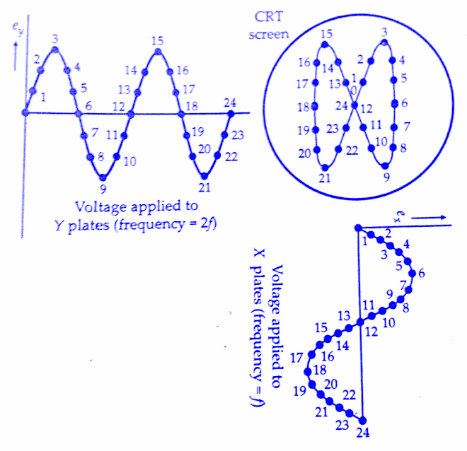
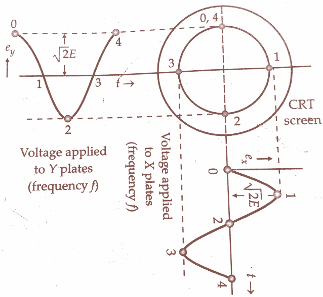
The two waves start at the same instant. Lissajous pattern may be constructed in the usual way and a 8 shaped pattern with two loops is obtained. If the two waves do not start at the same instant we get different patterns for the same frequency ratio.The Lissajous patterns for other frequency ratios can be similarly drawn. Some of these patterns are shown in the below figure.
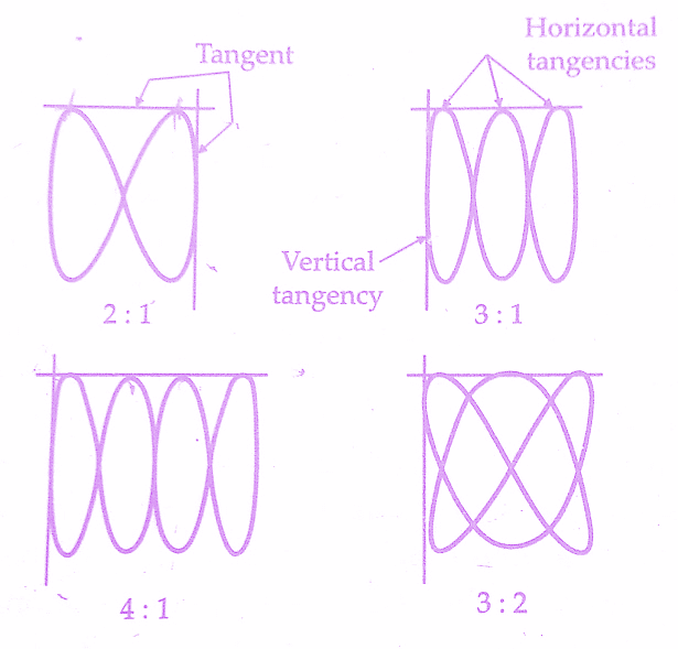
It can be shown that for all the above cases, the ratio of the two frequencies is
![Measurement of Phase & Frequency [Lissajous Patterns] of CRO](https://www.electricalengineeringinfo.com/wp-content/uploads/2016/11/Lissajous2BPatterns-of-Cathode2Bray2Boscilloscope-cro-3.jpg)
where fy = frequency of signal applied to Y plates
fx = frequency of signal applied to X plates
The above rule, however, does not hold for the Lissajous pattern with free ends as shown in the below figure(a). The simple rule mentioned above needs the following modifications :
This textbook “Electrical and Electronics Measurements by S. Chand” is the best in industry. Grab it now for very less price.
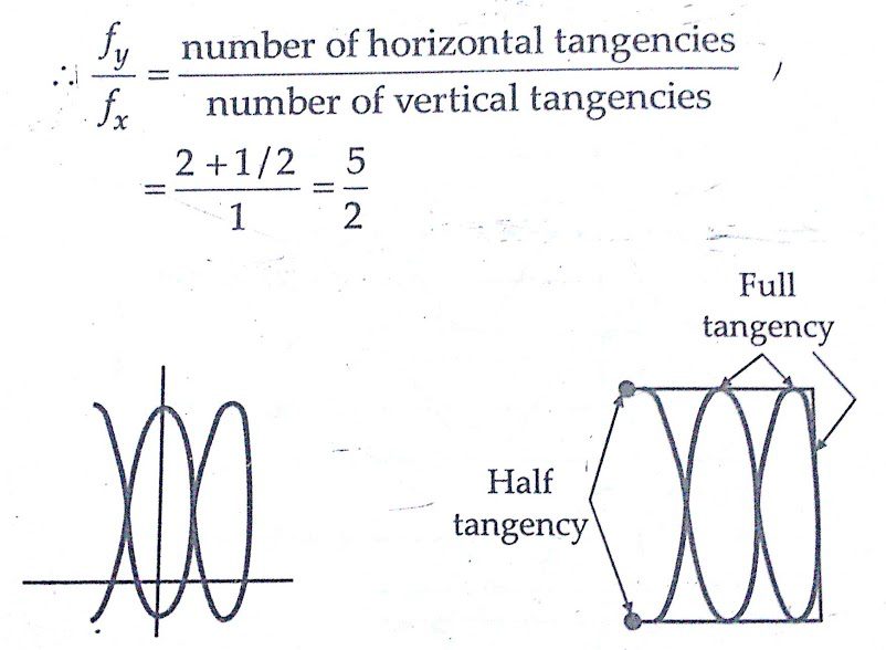
Two lines are drawn, one horizontal and the other vertical so that they do not pass through any intersections of different parts of the Lissajous pattern curve. The number of intersections of the horizontal and the vertical lines with the Lissajous pattern curve is individually counted. The frequency ratio is given by :
![Measurement of Phase & Frequency [Lissajous Patterns] of CRO](https://www.electricalengineeringinfo.com/wp-content/uploads/2016/11/Lissajous2BPatterns-of-Cathode2Bray2Boscilloscope-cro-2.jpg)
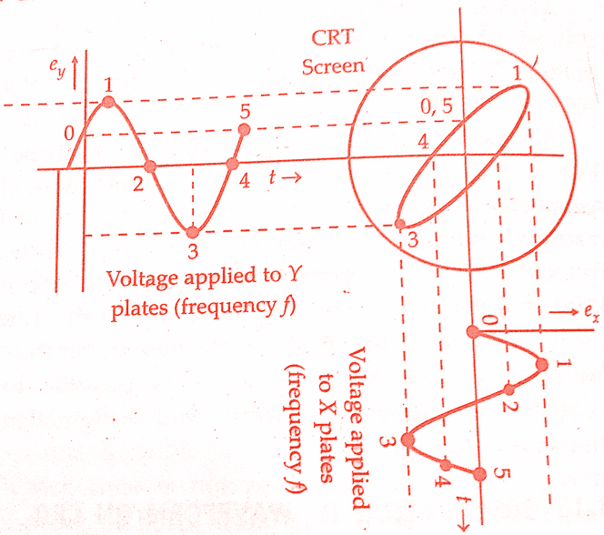
The application of this rule to below figure gives a frequency ratio fy/fx = 5/2.
The modified rule is applicable in all cases whether the Lissajous pattern is open or closed. The ratio of frequencies when open-ended Lissajous patterns are obtained can also be found by treating the open ends as half tangencies as shown in the below figure(b). The pattern of figure(a) is reproduced
There are some restrictions on the frequencies which can be applied to the deflection plates.One obviously, is that the CRO must have the bandwidth required for these frequencies. The other restriction is that the ratio of the two frequencies should not be such as to make the pattern too complicated otherwise measurement of frequency would become difficult. As a rule ratios as high as 10 : 1 and as low as 10 : 9 can be determined comfortably.
Conclusion:
Now here we have discussed the Measurement of Phase & Frequency (Lissajous Patterns) of CRO or Cathode ray oscilloscope. You can download this article as pdf,ppt.
I think you understood this article on Lissajous Patterns – frequency measurement and phase difference of CRO or Cathode ray oscilloscope.
Comment below for any Queries.