What is Cathode Ray Oscilloscope(CRO):
Cathode Ray Oscilloscope is a very useful and versatile laboratory instrument used for display, measurement and analysis of waveforms and other phenomena in electrical and electronic circuits.CRO’s are in fact very fast X-Y plotters, displaying an input signal versus another signal versus time. Cathode Ray Oscilloscopes operate on voltages. However, it is possible to convert current, strain, acceleration, pressure and other physical quantities into voltages with the help of transducers and thus to present visual representations of a wide variety of dynamic phenomena on CRO’s.In this, I will explain Cathode Ray Oscilloscope Working Principle & Construction.
Cathode Ray Oscilloscopes are used to investigate waveforms , transient phenomena and other time varying quantities from a very low frequency range to the radio frequencies. They are now available which can measure frequencies upto 1GHz and observer events as small as 20Hz in duration. Although , most oscilloscope are monochromatic, colour oscilloscope are finding increasing applications in computers and in television. Most present day oscilloscopes are capable of accepting two or more inputs displaying them simultaneously.
Construction of Cathode Ray Oscilloscope :
A cathode ray oscilloscope consists of a cathode ray tube which is the heart of the tube and some additional circuitry to operate the CRT.The main parts of a CRT
1) Electron gun assembly
2) Deflection plate assembly
3) Fluorescent screen
4) Glass envelope
5) Base
This textbook “Electrical and Electronics Measurements by S. Chand” is the best in industry. Grab it now for very less price.
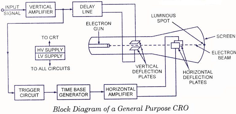
The below figure shows construction of Cathode Ray Oscilloscope.
1)Electron gun assembly :
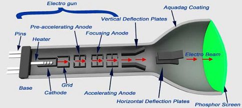
In cathode ray oscilloscope , this is the part from where electrons are born initially. It produces a sharply focused beam of electrons which are accelerated to high velocity. This focused beam of electrons strikes the fluorescent screen with sufficient energy to cause a luminous spot on the screen. After leaving the electron gun the electron beam passes through two pairs of electrostatic deflection plates.
Voltages applied to these plates deflects the beam. Voltage applied to one pair plates move the beam vertically up and down and the voltages applied to other pair of plates move the beam horizontally from one side to another. This two movements i.e horizontal and vertical are independent of each other and thus the beam may be positioned anywhere on the screen.
The working parts of a CRT are enclosed in an evacuated glass envelope so that the emitted electrons are able to move about freely from one end of the tube to other. The source of focused and accelerated beam is the electron gun, which emits electrons and forms them into a beam consists of a heater, cathode, a grid, a pre-accelerating anode, a focusing anode and accelerating anode.
In smaller CRT’s connections to the various electrodes are brought out through pins in the base or the tube as shown in the figure. Large and medium-sized high-performance tubes operate at very high voltages and these leads are usually bought out through the sides of the glass envelope.
Electrons are emitted from the indirectly heated cathode. A layer of barium and Strontium oxide is deposited on the end of the cathode which is a cylinder to obtain high emission of electrons at moderate temperatures. The typical values of current and voltage required by an indirectly heated cathode are 600 mA at 6. 3 V.
These electrons past through a small hole in the control grid. This control grid is usually a Nickel cylinder with a centrally located hole coaxial with the CRT axis. This is usually a metal cup of low permeability Steel about 15 mm in diameter 15 mm long. And an aperture of about 0.25 mm is drilled in the cap of the grid for the electrons to flow through. The intensity of the electron beam depends upon the number of electrons emitted from the cathode.
The grid with its negative bias controls the number of electrons emitted from the cathode and hence the intensity is controlled by the grid. The electrons emitted from the cathode and passing through the hole in the control grid are accelerated by the high positive potential which is applied to the pre-accelerating and accelerating anodes.
The electron beam is focused by the focusing anode. The accelerating and focusing anodes are cylindrical in form with small openings located in the centre of each electrode coaxial with the tube axis. After leaving the focusing anodes, the electron beam passes through the vertical and horizontal deflection plates and then goes on to the fluorescent screen. The pre-accelerating and the accelerating anode are connected to a common positive high voltage of about 1500v. The focusing anode is connected to a lower adjustable voltage of 500v.
Circuit diagram of Cathode Ray Oscilloscope:
Cathode Ray Oscilloscope Working Principle:
There are two methods of focusing an electron beam :
1) Electrostatic focusing
2) Electromagnetic focusing
The CRO uses electrostatic method of focusing as compared to a TV picture tube which employes electromagnetic focusing. Here we will discuss Electrostatic focusing only.
1)Electrostatic focusing:
The figure shows an electron at rest placed in an electric field produced parallel plates. Force on the electron is,
F = – e.E newtons
where E = electric field intensity ; V/m
e = charge of electron = 1.602 * 10^(-19)
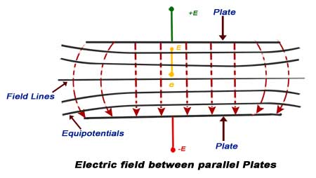
The minus sign indicates that the force acts in the opposite direction to that of the field. The above discussion is valid only if the electron is situated in a field of uniform intensity. In practice, however, the field is not uniform. The lateral repulsion of the electric field lines causes a spreading of space between the lines, resulting in curved field lines at the ends. Thus the field intensity will be less at the ends. The figure also shows equipotential surfaces, indicated by solid Lines.
Since the force is in a direction opposite the field and the equipotential surfaces are perpendicular to the field, the force on an electron is in a direction normal to the equipotential surfaces. The figure shows two concentric cylinders with a potential applied between them. Lateral repulsion again causes the spreading of the flux lines producing a field as shown. The equipotential surfaces are shown as solid lines. It is clear from the below diagram that the equipotential surfaces are curved.
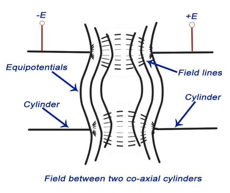
Let us consider the region on the two sides of an equipotential surface S as shown in the figure. The potential on the left side of the surface is – V and on the right side is +V. Let an electron moving in a direction AB enter the area to the left of S.This electron experiences of force which is normal to the surface S and is thus accelerated.
Since the force acts in a direction normal to the surface, it is the normal component of velocity that is increased after refraction while the tangential component remains the same.
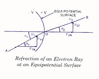
The tangential components are
Vt1 = V1 sinθi and Vt2 = V2 sinθ
Now Vt1 = Vt2 or V1 sinθi = V2 sinθr
sinθi/sinθr = V2/V1
where V1 = Initial velocity of electrons
V2 = Velocity of electrons after leaving surface S
θi = angle of incidence
θr = angle of refraction
This textbook “Electrical and Electronics Measurements by S. Chand” is the best in industry. Grab it now for very less price.
2)Deflection plate assembly :
This explains Cathode Ray Oscilloscope Working Principle. Electron beam after leaving the electron gun passes through two pairs of deflection plates. One pair of plates is mounted horizontally and produces an electric field in the vertical plane. This place produces a vertical deflection and is called vertical deflection plates or Y plates. The other pair of plates is mounted vertically and produces a horizontal deflection. This pair of plates is called horizontal deflection plates or X plates. Plates are flared so as to allow the beam to pass through them without striking the plates.
i)Vertical deflection system :
The signals to be examined are usually applied to the vertical or Y deflection plates through an input attenuator and a number of amplifier stages. The vertical amplifier is required because the signals are not strong enough to produce measurable deflection on the CRT screen. When High Voltage signals are to be examined, they must be attenuated to bring them within the range of vertical amplifiers. The vertical amplifier output is also applied to the synchronizing amplifier through the synchronizer selector switch in the internal position.
ii)Horizontal deflection system :
The horizontal deflection plates are fed by a sweep voltage that provides time base. The horizontal plates are supplied through an amplifier but they can be fed directly when voltage is of sufficient magnitude. When external signals are to be applied to the horizontal deflection system they can also be fed through the horizontal amplifier via the sweep selector switch in the external position.When the sweep selector switch is in the internal position the horizontal amplifier receives an input from the sawtooth sweep generator which is triggered by the synchronising amplifier.
3)Fluorescent screen:
The front of the CRT is called the faceplate. It is flat for screen sizes up to about 100mm * 100mm and is slightly curved for larger displays. Faceplate is formed by pressing molten glass in a mould and then annealing it. Some CRTs have a faceplate which is made from fibre optics. The inside surface of the faceplate is coated with phosphor. This consists of very pure inorganic crystalline phosphor crystals about 2 – 3 microns in diameter to which traces of other elements called activators are added.
Activator in current use are metals such as silver, manganese, Copper and chromium. When an electron beam strikes phosphor crystals it raises their energy level. This is called as cathodoluminescence. Light is emitted during phosphor excitation and this is called fluorescence. When the electron beam is switched off the phosphor crystals return to their initial states and release a quantum of light energy. This is called phosphorescence or persistence.
The writing speed of a phosphor is measured by its fluorescence rise time which is the time from the beginning of excitation to reach 90% of the maximum emission state and by the decay time which is time to fall from the maximum state to the 10% level. Writing speed is determined by the phosphor type, crystal size, impurity content and manufacturing process.
The bombarding electrons when strikes the screen release secondary electrons. The secondary electrons are collected by an aqueous solution of Graphite called Aquadag, which is connected to the second anode, the collection of secondary electrons is necessary to keep the CRT screen in a state of electrical equilibrium.
4)Glass envelope:
The working parts of a CRT are enclosed in an evacuated glass envelope so that the emitted electrons are able to move freely from one end of the tube to the other.
5)Base:
Through this base, connections are made to various parts from cathode ray oscilloscope. Pins come out of this base and external connections are made.