The availability of electronic circuitry at low cost has enabled many digital features to be added to analog oscilloscopes.We discuss Digital Storage Oscilloscope(DSO) working principle & block diagram.Examples of these are : generation of a trigger after an elapsed time or after a count of a number of pulses ; digital display of the parameters; integral digital voltmeter and counter : remote control.However, the basic oscilloscope still remains analog, and uses an analog storage CRT, as described in the article Construction of cathode ray oscilloscope(CRO).
Digital Storage Oscilloscope(DSO) Working Principle:
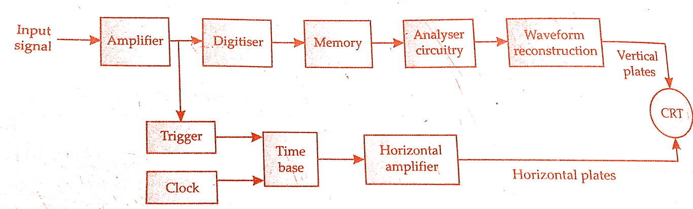
A digital storage oscilloscope digitises the input signal, so that all subsequent signals are digital.A conventional CRT is used, and storage occurs in electronic digital memory.The figure below shows a constructional block diagram of a basic digital storage oscilloscope.The input signal is digitised and stored in memory in digital form. In this state it is capable of being analysed to produce a variety of different information.To view the display on the CRT the data from memory is again constructed in analog form.
Must Read:
- Construction and Operation of Enhancement type MOSFET | MOSFET
- Construction and Working principle of Depletion type MOSFET
- Electrical resistor | Materials used in precision Resistors
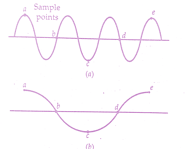
Digitising occurs by taking a sample of the input waveform at periodic intervals. In order to ensure that no information is lost, sampling theory states that the sampling rate must be at least twice as fast as the highest frequency in the input signal. If this is not done then aliasing will result, as shown in the figure below .
This requirement for a high sampling rate means that the digitiser, which is an analog to digital converter, must have a fast conversion rate. This usually requires expensive flash analog to digital converters, whose resolution decreases as the sampling rate is increased. t is for this reason that the bandwidth and resolution of a digital storage oscilloscope(dso) is usually limited by its analog to digital converter.
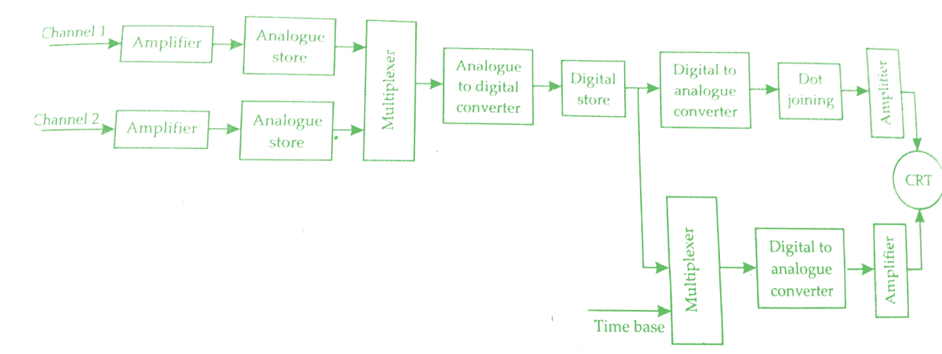
One method of overcoming the need for a high performance converter is to use an analog store, as in the figure below.The input signals are sampled, and these are stored in an analog shift register.They can then be read out at a much slower rate to the analog to digital converter, and the results stored in a digital store.
This method allows operation at up to 100 mega samples per second, and has the advantage that a low cost analog to digital converter can be used, whose resolution does not decrease as the sampling rate is changed.The disadvantage is that the oscilloscope cannot accept data during the digitising period, so it has a blind spot. At low sweep speed operations, it is usual to switch out the analog memory, feeding the analog to digital converter in real time.
Many different input channels are used with digital storage oscilloscopes.However if all these channels share a common store, through a multiplexer, then the memory available to each channel is reduced.Digital storage oscilloscopes with up to 40 channels are commercially obtainable, with a storage capability of 25000 dots.Several oscilloscopes also have floppy disc storage capability to allow non volatile storage of waveforms, which can later be recalled into the oscilloscope and manipulated.
Waveform Reconstruction of Digital Storage Oscilloscope(DSO):
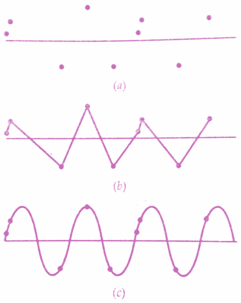
Although the input signal may be sampled at greater than twice the highest signal frequency, aliasing can still result when the output is present as a series of dots, corresponding to the sampled values.This is illustrated in the figure(a) below, where the user’s mind connects together the dots which are physically closest to each other, rather than those which are closest on the time scale.
In the illustration of the figure(a), it is difficult to visualise the final waveform.And digital storage oscilloscopes generally have the facility to interpolate between the dots, if required by the user.Two techniques are used,
(i)Linear interpolation
(ii)Sinusoidal interpolation
In linear interpolation, shown in the figure(b) a straight line is used to connect the dots together.This works well on a pulsed or square waveform, but not on a sinusoidal wave, the figure(c) shows that sinusoidal interpolation gives a much better fit for sine waves, although it is not suitable for pulse or square waves.
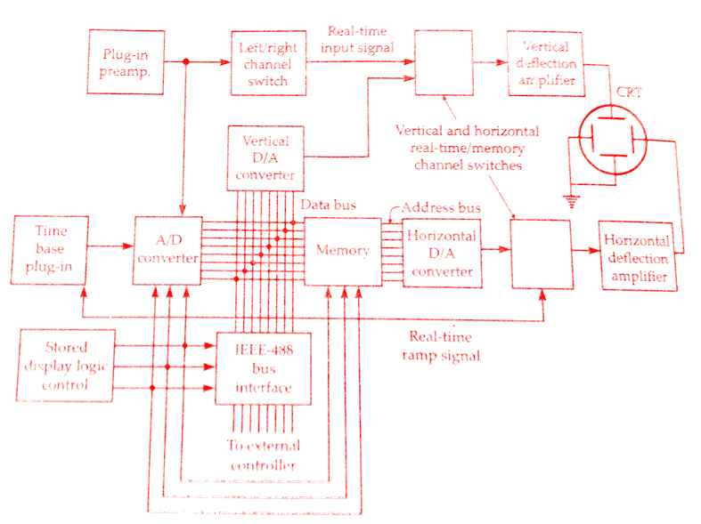
Another practical block diagram of digital storage oscilloscope(dso) is shown in the figure below.
Another problem with the sampling technique used in digital storage oscilloscopes is that it can miss short term transient, or ‘glitches’, which occur in between the sample points. To overcome this problem envelope mode oscilloscopes may be used. These have special logic circuitry which causes the sample and digitising circuitry to run at a high speed, independent of the setting of the display time.
At each sample the value is compared with the previous stored sample, and the higher tor lower) value is stored. This is continued for the screen interval, to that for that interval the highest and lowest points are always stored.For example, suppose that an oscilloscope digitises every 2 ms, at a given sweep speed. If a 0.1 ms transient were to occur there is a high probability that a conventional digital storage oscilloscope would miss it.
In an envelope mode digital storage oscilloscopes, the input would be sampled, say, every 200 ns, but only the highest, or lowest, values that occur within a 2 ms window would be stored in memory. Therefore the transient would be recorded. The sample rate of the oscilloscope is controlled by the time setting of the oscilloscope,but the analog to digital converter runs very faster.
Block Diagram of digital storage oscilloscope(DSO):
Conclusion:
Now here we have discussed the entire concept of Digital Storage Oscilloscope (DSO) block diagram and working principle. Soon I will be writing an article on Digital Storage Oscilloscope(DSO) functions, applications and its advantages. You can download this article as pdf, ppt.
Comment below for any Queries.