Transfer Function of Pneumatic System:
The pneumatic system uses the compressible fluid as a working medium usually air. In pneumatic systems, compressibility effects of gas cannot be neglected and hence dynamic equations are obtained using conservation of mass. In this, we will derive the transfer function of the pneumatic system.
In pneumatic systems, change in fluid inertia energy and the fluid’s internal thermal energy are assumed negligible. In a pneumatic system which employs compressible fluid as working fluid, the mass and volume flow rates are not readily interchangeable and the analysis of gas flow is more complicated.
The pneumatic devices involve the flow of gas or air, through connected pipe tines and pressure vessels. Hence the variables of pneumatic system are mass flow rate, qm and pressure, P. The mass now rate is through variable and it is analogous to current. The pressure is across variable and it is analogous to voltage.
The two basic elements of the pneumatic system are resistance and capacitance. The restrictions in the pipes and valves offer resistance to gas flow.
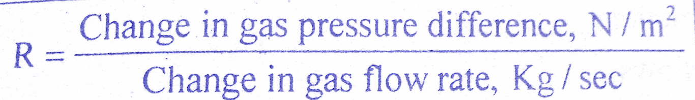
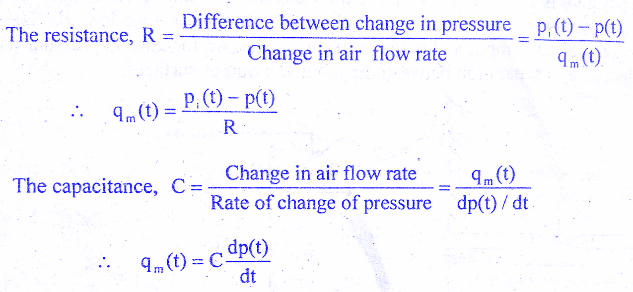
The gas flow resistance, R is defined as the rate of change in gas pressure difference for a change in gas flow rate. We will learn about the derivation of the transfer function of the Pneumatic system.
![]()
Must Read:
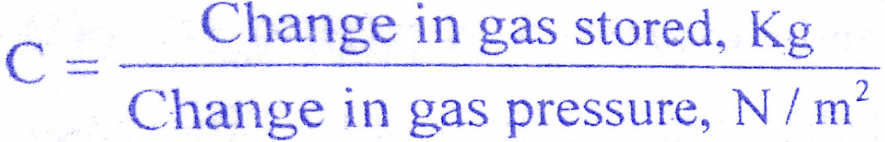
The pneumatic capacitance is defined for a pressure vessel and depends on the type of expansion process involved. The capacitance of a pressure vessel may be defined as the ratio of change in gas stored for a change in gas pressure.
Pneumatic devices are employed in guided missiles, aircraft systems, automation of production machinery and in many other fields as automatic controllers.
Advantages of the pneumatic system:
The advantages of the pneumatic system are,
1)The air or gas used is non-inflammable and so it offers safety from fire hazards.
2)The air or gas has negligible viscosity, compared to the high viscosity of hydraulic fluids.
3)No return pipelines are required since air can be let out, at the end of the device work cycle.
The disadvantage in the pneumatic system is that the response is slower than that of hydraulic systems, because of the compressibility of the working fluid.
Transfer function of Pneumatic System derivation:
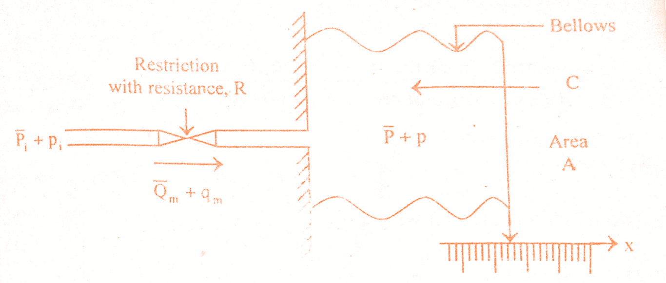
A simple pneumatic system is shown in the below figure and it consists of pneumatic bellows in line with the restriction. The pneumatic bellows consist of a hollow chamber with thin pneumatic walls. The sidewalls of bellows are corrugated and the input and output surface is flat. An increase in pressure within the bellows results in an increase in separation between the input and output surfaces.
 |
| transfer function of the pneumatic system |
Let Pi = Steady state value of input air pressure
pi = Increase in the pressure air source
P = Steady State value or pressure inside the bellows
p =Increase in pressure inside the bellow
Qm = Steady state value of airflow rate
qm = Area of each flat surface of the bellows
R = Resistance of the restriction
C = Capacitance of the bellows
x= Displacement of the movable surface of the bellows
Let the pressure of air source be increased from its steady-state value by an amount pi. This results in an increase in the airflow by qm and an increase in the pressure inside the bellows by p. Due to the increase in pressure, there will be a displacement of the movable surface of the bellows, by an amount x. Here, the terms pi, qm, p and x are all functions of time, t and so can be expressed as pi(t), qm(t), p(t) and x(t). Let us get into the transfer function of the pneumatic system derivation.
Must Read:
The force exerted on the movable surface of the bellows is proportional to the increase in pressure inside the bellows, i.e, fb ∝ p(t).
The force exerted on the movable surface of the bellow, fb=A p(t)
The force opposing the movement of the flat surface of bellow walls is proportional to displacement i.e, fo ∝ x(t).
Force opposing the motion, fo= K x(t)
where K Constant representing the stiffness of bellows.
At steady state the above two forces are balanced,
fb = fo
A p(t) = K x(t)
On equating the two equations of qm(t) we get,
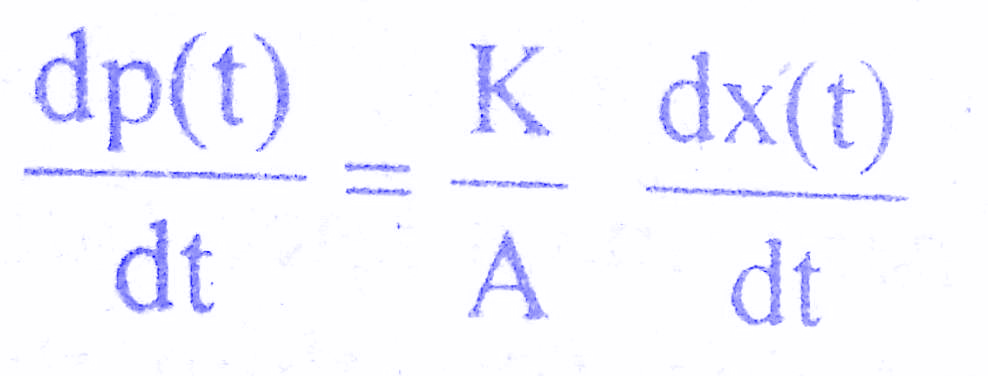
From above equation we get , p(t) = K/A x(t)
Must Read:
On differentiating above equation w.r.t t , we get,
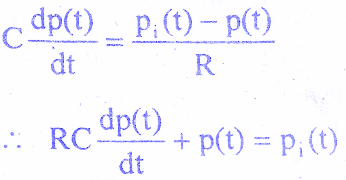
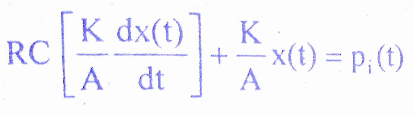
On substituting for p(t) and dp(t)/dt , we get,
On taking Laplace Transform with zero initial conditions, we get,
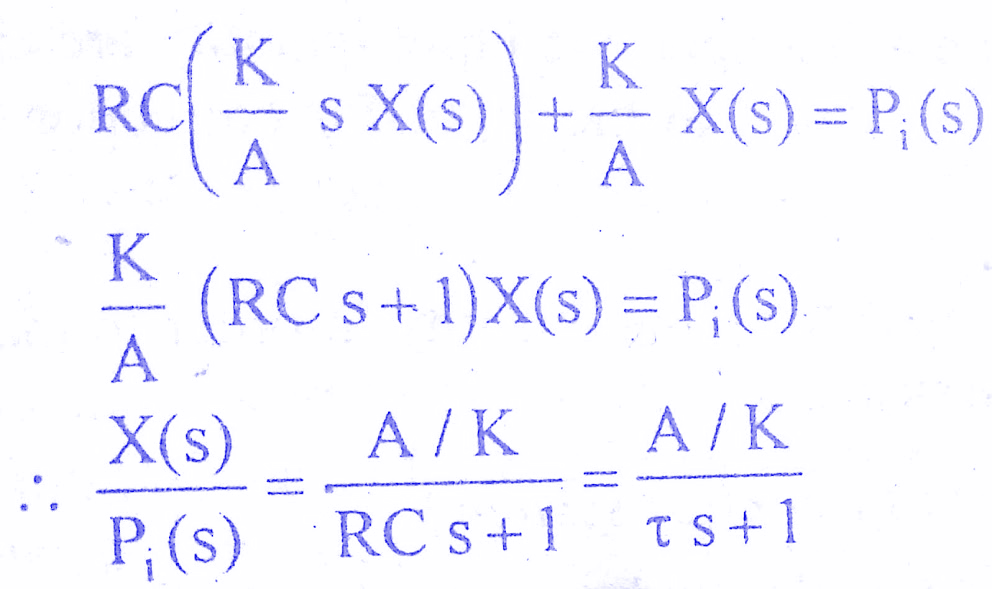
where t = RC = Time constant of the system
The above equation is the required transfer function of the pneumatic system.
Conclusion:
In this post, we have learnt the Transfer Function of Pneumatic System. You can download this article as pdf, ppt.
Comment below if you have any queries!
Good