Transfer Function Of Synchros:
The term synchro is a generic name for a family of inductive devices which works on the principle of a rotating transformer(Induction motor). The trade names for synchros are Selsyn, Autosyn and Telesyn. Basically, they are electro-mechanical devices or electromagnetic transducers which produces an output voltage depending upon the angular position of the rotor. Here we will learn the transfer function of Synchros.
A synchro system is formed by the interconnection of the devices called the synchro transmitter and the synchro control transformer. They are also called Synchro pair. The synchro pair measures and compares two angular displacements and its output voltage are approximately linear with an angular difference of the axis of both the shafts. They can be used in the following two ways,
1. To control the angular position of the load from a remote place/long distance.
2.For automatic correction of changes due to the disturbance in the angular position of the load.
Must Read:
Construction of Synchro Transmitter:
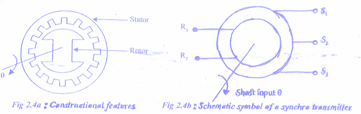
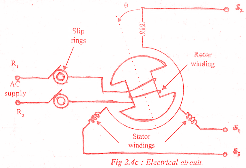
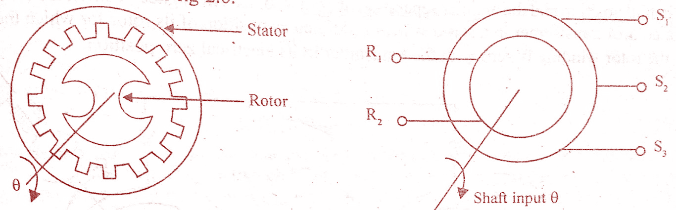
The constructional features, electrical circuit and a schematic symbol of synchro transmitter are shown in the below figure. The two major parts of the synchro transmitter are stator and rotor. The stator is identical to the stator of the three-phase alternator.
It is made of laminated silicon steel and slotted on the inner periphery to accommodate a balanced three-phase winding. The stator winding is the concentric type with the axis of three coils 120° apart. The stator winding is star connected ( Y-connection). This basic construction will help you derive the transfer function of Synchros.
The rotor is of dumbbell construction with a single winding. The ends of rotor winding are terminated on two slip rings. A single-phase ac excitation voltage is applied to the rotor through slip rings.
Working principle of Synchro Transmitter:
When the rotor is excited by ac voltage, the rotor current flows, and a magnetic field is produced. The rotor magnetic field induces an emf in the stator coils by transformer action. The effective voltage induced in any stator coil depends upon the angular position of the coil’s axis with respect to the rotor axis.
Let,
er = Instantaneous value of ac voltage applied to rotor.
es1,es2,es3 = Instantaneous value of emf induced in stator coils S1 ,S2,S3 with respect to neutral respectively.
Er = Maximum value of rotor excitation voltage.
ω = Angular frequency of rotor excitation voltage.
Kt = Turns ratio of stator and rotor windings.
Kc = Coupling coefficient.
θ = Angular displacement of rotor with respect to reference.
Let, the instantaneous value of rotor excitation voltage, er = Er sin ωt
Let the rotor rotates in an anticlockwise direction. When the rotor rotates by an angle,θ EMFs are induced in stator coils. The frequency of induced emf is the same as that of rotor frequency. The magnitude of induced EMFs is proportional to the turns ratio and coupling coefficient. The turns ratio, Kt is a constant, but coupling coefficient, K is a function of rotor angular position.
Induced emf in stator coil = Kt Kc Er sin ωt
Let es2 be reference vector. With reference to the above figure, when θ = 0, the flux linkage of coil S2 is maximum and when θ = 90°, the flux linkage of coil S2 is zero. Hence the flux linkage of coil S2 is a function of cosθ (i.e., kc= Kt cosθ for coil S2). The flux linkage of coil s3 will be maximum after a rotation of 120° in the anticlockwise direction and that of S1 after a rotation of 240°.
Coupling coefficient,Kc for S2 = K1 cos θ
Coupling coefficient,Kc for S3 = K1 cos (θ-120°)
Coupling coefficient,Kc for S1 = K1 cos (θ-240°)
Hence the EMFs of stator coils with respect to neutral can be expressed as follows.
es2 = Kt K1 cos θ Er sin ωt = K Er cos θ sin ωt
es3 = Kt K1 cos (θ-120°) Er sin ωt = K Er cos (θ-120°) sin ωt
es1 = Kt K1 cos (θ-240°) Er sin ωt = K Er cos (θ-240°) sin ωt
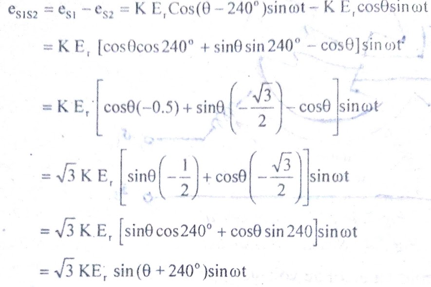
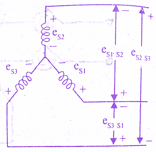
With reference to the below figure by Kirchoffs voltage law the coil-to-coil emf can be expressed as ,
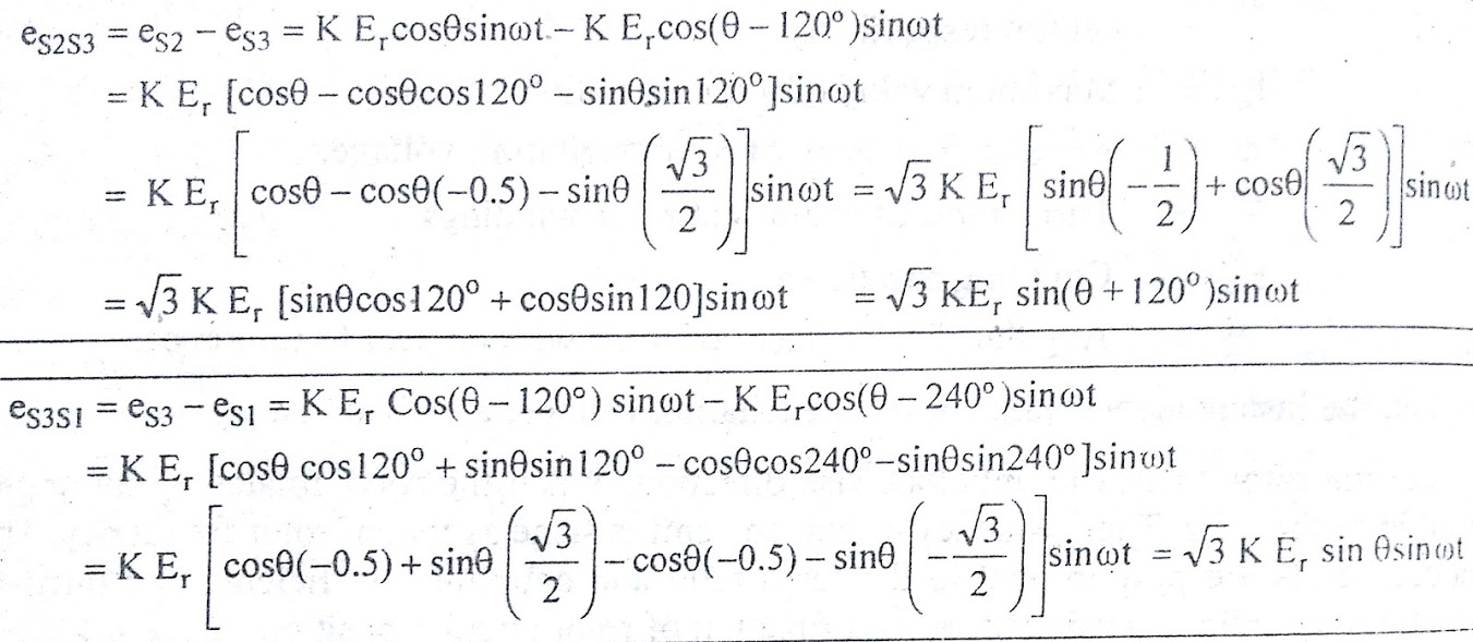
eS1S2 = eS1 – eS2 = √3 KEr sin (θ + 240° )sin ωt
eS2s3 = eS2 – es3 = √3 KEr sin (θ + 120° )sin ωt
eS3s1 = eS3 – es1 = √3 KEr sin θ sin ωt
Must Read:
When θ = 0, from equation the above equation we can say that maximum emf is induced in coil S2.But from equation above ,it is observed that the coil-to-coil voltage es3s1 is zero. This position of the rotor is defined as the electrical zero of the transmitter.
The electrical zero position is used as reference for specifying the angular position of the rotor. The input to the synchro transmitter is the angular position of its rotor shaft and the output is a set of three stator coil-to-coil voltages. By measuring and identifying the set of voltages at the stator terminals.
It is possible to identify the angular position of the rotor [A device called synchro/digital converter is available to measure the stator voltages and to calculate the angular measure and then display the direction and angle of rotation of the rotor].
Construction of Synchro Control Transformer:
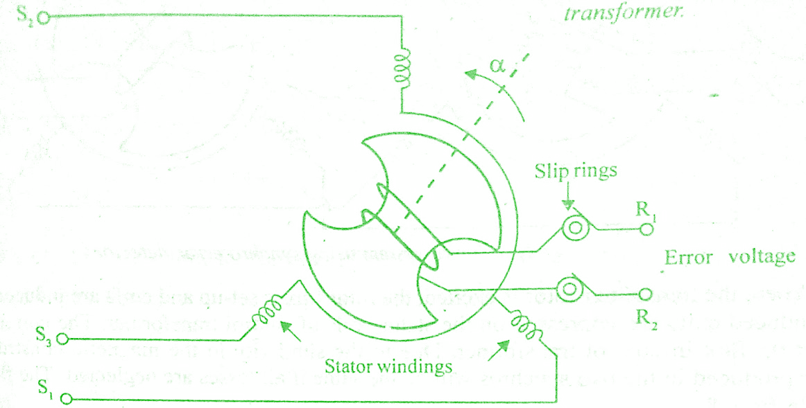
The construction of synchro control transformer is similar to that of synchro transmitter except the shape of rotor. The rotor of the control transformer is made cylindrical so that the air gap is practically uniform. This feature of the control transformer minimizes the changes in the rotor impedance with the rotation of the shaft. The constructional features, electrical circuit and a schematic symbol of control transformer are shown in the below figure.
Working of Synchro Control Transformer:
The generated emf of the synchro transmitter is applied as input to the stator coils of control transformer. The rotor shaft is connected to the load whose position has to be maintained at the desired value. Depending on the current position of the rotor and the applied emf on the stator, an emf is induced on the rotor winding. This emf can be measured and used to drive a motor so that the position of the load is corrected.
Synchro as error detector:
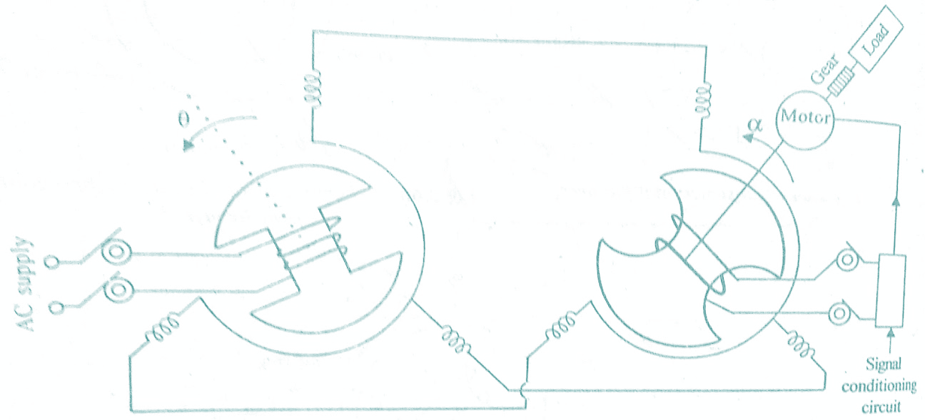
The synchro error detector is formed by the interconnection of a synchro transmitter and synchro control transformer. In this arrangement, the stator leads of the transmitter are directly connected to the stator leads of the control transformer.The angular position of the transmitter-rotor is the reference input (or the input corresponding to the desired output) and the rotor is excited by ac supply with frequency, ω.
The control transformer rotor is connected to a servo motor and to the shaft of the load, whose position is the desired output. The induced emf (error voltage) available across the rotor slip rings of control transformer is measured by a signal conditioning ciruit.The output of signal conditioning circuit is used to drive motor so.that desired load position is achieved. A simple schematic diagram of synchros as error detector is shown in the below figure.
Initially, the shafts of transmitter and control transformer are assumed to be in aligned position. In this position, the transmitter rotor will be in electrical zero position and the control transformer rotor will be in null position and the angular separation of both rotor axis in aligned position is 90°.
The null position of a control transformer in a servo system is defined as position of its rotor for which the output voltage on the rotor winding is zero with the transmitter in its electrical zero position.
When the transmitter rotor is excited, the rotor flux is set-up and emfs are induced in stator coils, These induced EMFs are impressed on the stator coils of control transformer.The currents in the stator coils set up flux in control transformer. Due to the similarity in the magnetic construction, the flux patterns produced in the two synchros will be the same if all losses are neglected. The flux patterns are shown in the below figure.
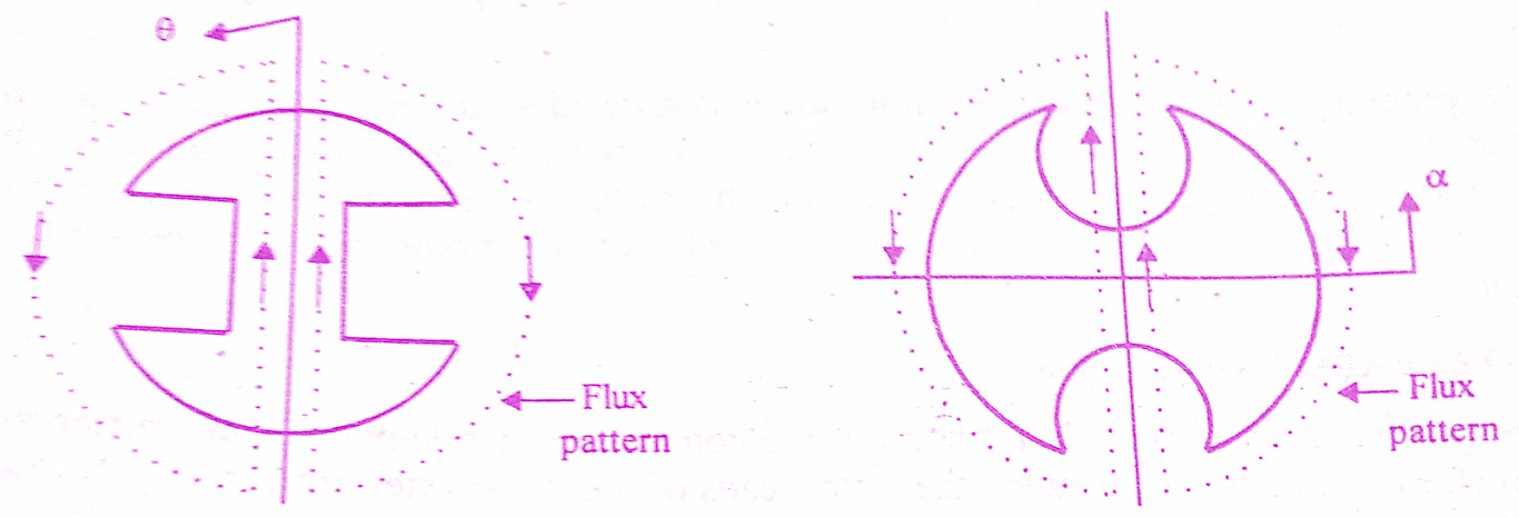
Let the rotor of the transmitter rotate through an angle θ from its electrical zero position. Now the rotor of the control transformer will rotate in the same direction through an angle α from its null position. The net angular separation of the two rotors is equal to (90-θ+α) and the voltage induced in the control transformer rotor is proportional to the cosine of this angle.
The error voltage is amplified and used to drive a servo motor.The motor drives the shaft of the synchro control transformer until it comes to a new aligned position at which the error voltage is zero.
Must Read:
Transfer Function Of Synchros:
Voltage across slip rings of control transformer (modulated error voltage)
em = K’ Er cos(90 – θ + α) sin ωt
= K’ Er cos(90 – (θ – α)) sin ωt
= K’ Er sin(θ – α) sin ωt
where K’ is a proportional constant
Let φ(t) = θ – α
For small values of φ(t), sin(θ – α) = sin φ(t) ≈ φ(t)
em = K’ Er φ(t) sin ωt
From the above equation we can say that the output voltage of the synchro error detector is a modulated signal with carrier frequency, ω (which is same as supply frequency of the transmitter rotor).
The magnitude of the modulated carrier wave is proportional to φ(t) and the phase reversals of the modulated wave depend on the sign of φ(t).The signal conditioning circuit demodulates the voltage available across slip rings and develops a demodulated and amplified error voltage to drive the motor.
The demodulated error voltage, e = Ks φ(t)
where K = Sensitivity of synchro error detector in Volts/deg.
On taking Laplace transform of equation above we get,
E(s) = Ks φ(s)
∴ E(s)/φ(s) = Ks
The equation above is the transfer function of the Synchro error detector.
Conclusion:
In this post, we have learnt Transfer Function & Construction, Working Principle Of Synchros transmitter. You can download this article as pdf, ppt.
Comment below if you have any queries!