Measurement of Capacitance:
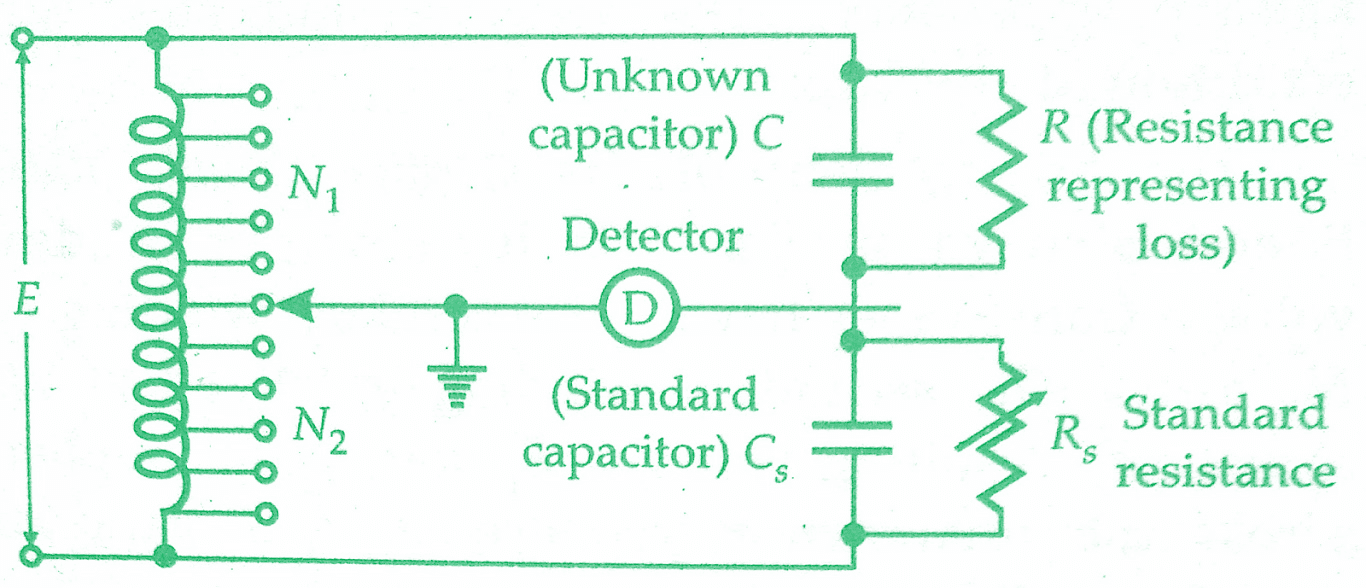
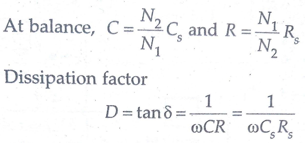
A circuit for measurement of capacitance By Transformer Ratio Bridge is given in the below figure.An unknown capacitance C is measured in comparison with a standard capacitance C, which is assumed to be perfect.Resistance R represents the loss of the capacitor.Since for balance, the magnitude and phase of the currents passing through the detector should be the same, a variable standard resistance is connected in parallel with the standard capacitor.
Must Read:
Measurement of Phase Angle:
A circuit for measurement of small phase angles by ratio transformers bridge is shown in the below figure.An RC circuit is used where the capacitance is variable in order to get phase shift.The value of resistance should be large in order that there are no loading effects on the ratio transformer.The capacitance is changed till the detector indicates null.
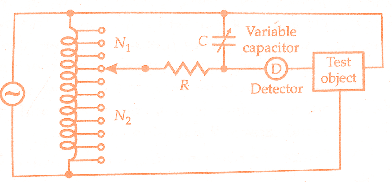
Phase angle ∮ = tan⁻¹(-ωRC)
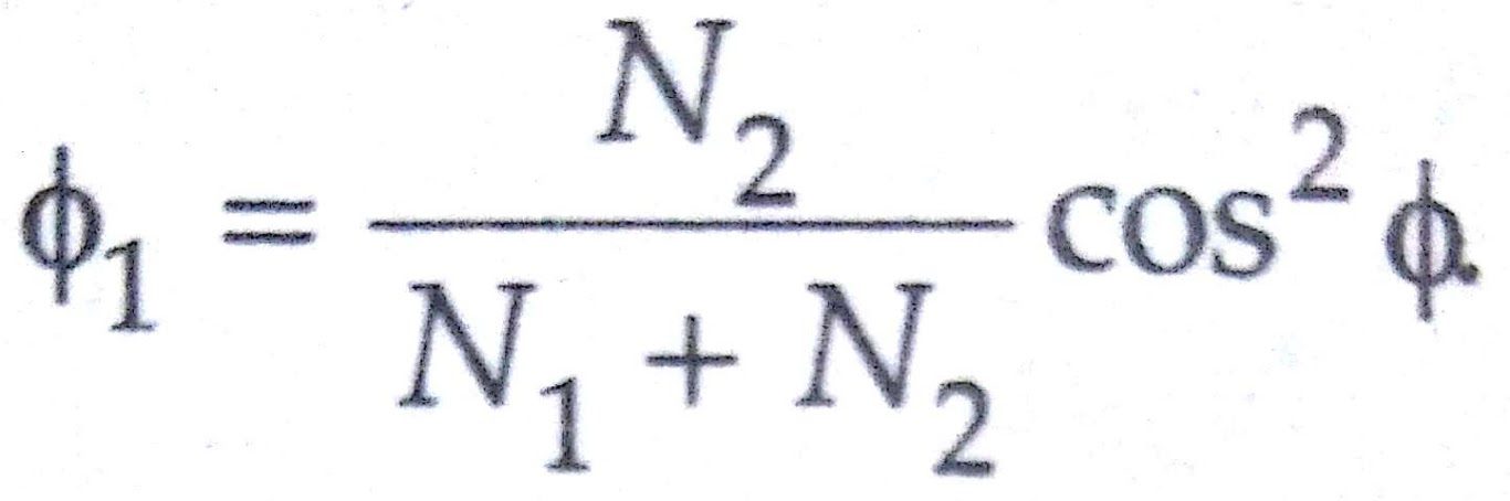
The magnitude of in-phase component is
Transformer Double Ratio Bridges:
The transformer ratio bridges described till now in this chapter are similar to the conventional ac bridges in the sense that the balance conditions are indicated when the voltage across the detector is zero and therefore, the current through the detector is zero.
An alternate way of indication of balance is that the current flowing through the unknown impedance is equal and opposite to that through the standard or known impedance.The detector indicates this condition of equality.
The arrangement of Transformer Double Ratio Bridges is shown in the below figure.It consists of an ideal voltage transformer having a secondary winding of N1 turns.The secondary winding is tapped at N2 turns.The resulting voltages E1 and E2 are applied across the unknown impedance, Z, and standard impedance, Zs, respectively.
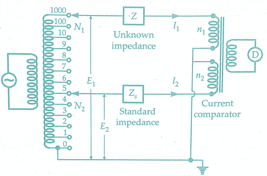
The two voltages E1 and E2 produce currents I1 and I2 respectively. These currents flow in the windings n1 and n2 of a current comparator.The two mmfs n1I1 and n2I2 produce fluxes in the core of the comparator.The two fluxes oppose each other and when there is no flux in the core, no emf is induced in the secondary winding of this comparator and the detector D indicates the null condition.
Must Read:
At balance, the two mmfs, n1I1 = n2I2
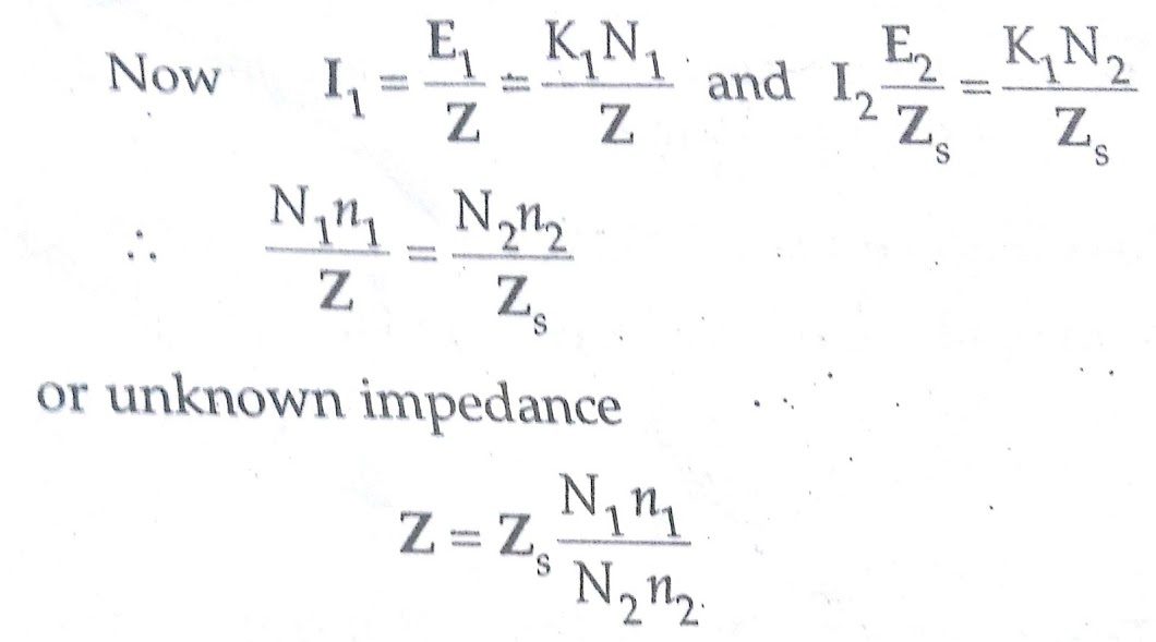
The balance is obtained by changing the setting of N2.
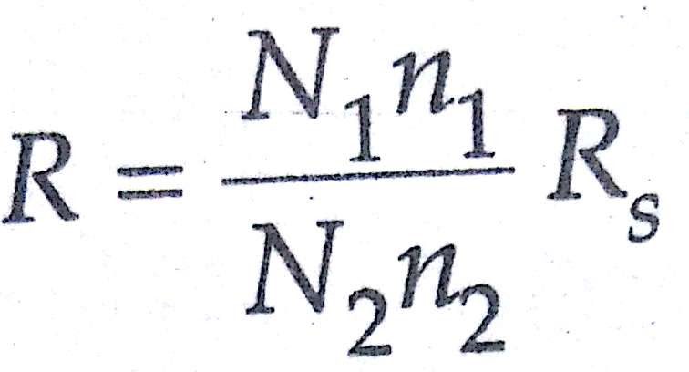
If the unknown impedance is a pure resistance R, a standard resistance Rs is required for obtaining balance
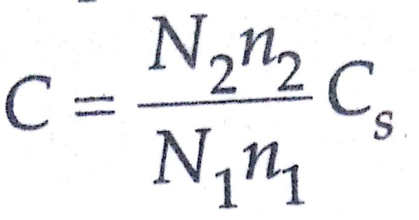
If the unknown impedance is a pure capacitance C, a standard capacitor Cs is required for balance,
Above equation can also be converted to a form similar to that of Eqn. 16.78. This is done by using conductance in place of resistance.
Unknown conductance,
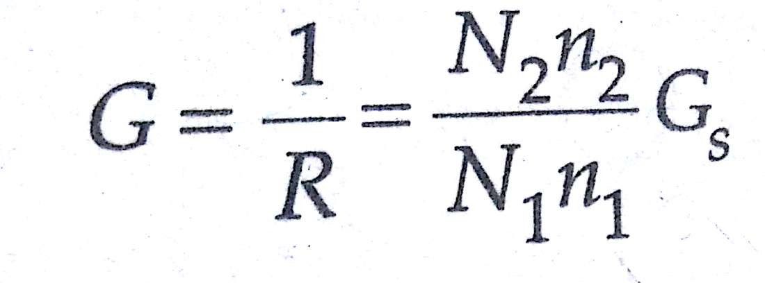
where Gs is the standard conductance.
In practice, the capacitors are not perfect, the losses being represented by a conductance in parallel with the capacitance.Therefore, the balance has to be obtained both for resistance as well as for capacitance.In other words, mmf equality for both magnitude as well as for phase has to be obtained in order to get balance.A circuit used of measurement of imperfect capacitor in terms of the standard capacitor and standard conductance is shown in the below figure.
Under balance,
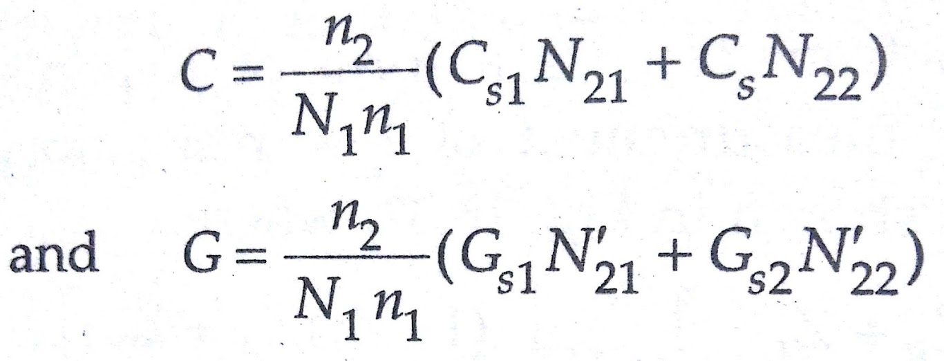
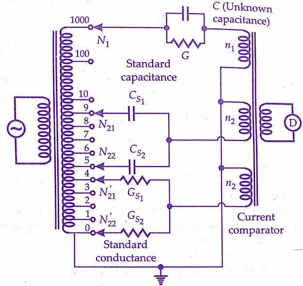
It is clear from the above equations that the transformer double ratio bridge allows the reactive and resistive components of an unknown to be adjusted independently of each other (capacitive balance can be had by changing N21 and N22 while resistive balance can be obtained by changing N‘21 and N’22).This property of independent balance facilitates the use of this bridge in a very wide range of applications.
Must Read:
Measurement of Inductance:
The circuit for measurement of inductance is the same as that for measurement of capacitance except that the unknown capacitance is replaced by the unknown inductance.
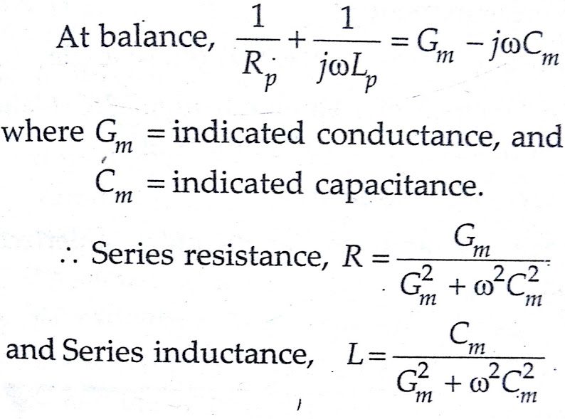
In order that independent balance of the resistive and reactive mmfs can be obtained any inductive circuit must be considered as a two terminal network, the components of which are in parallel.The mmf due to the resistive component of the unknown may then be opposed by that through the conductance standard.On the other hand, the mmf due to inductive component of the unknown must be balanced due to capacitance standard.
In order to obtain mmf balance due to unknown inductance and the standard capacitance, it is necessary to reverse the comparator winding connected to the standard capacitor.This condition of bridge operation is normally indicated by addition of a negative sign to the display of capacitance Cm.Suppose an inductance Lp in parallel with a resistance Rp represents the actual inductor having an inductance L in series with a resistance R.
Measurement of Components in ‘SITU’:
One of the greatest advantages of double ratio transformer bridges is their capability to measure the values of the components while they remain connected in the circuit.The below figure shows a circuit for measurement of an unknown impedance Z.
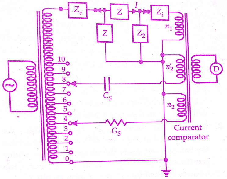
If the ratio transformers are considered ideal the values of impedances Ze and Zi can be assumed to be zero and the voltage applied to the unknown impedance Z is not affected by current flowing in impedance Z1.Also, all the current flowing through Z would flow into winding as :
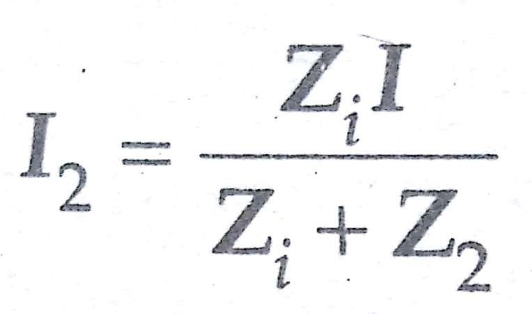
The value of unknown approximately given by :
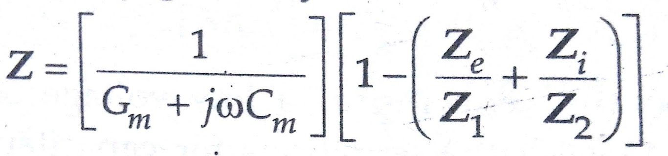
In practice impedances, Ze and Zi have small finite values and corrections must be applied for this.In order that corrections be applied Ze and Zi must be determined.
Conclusion:
In this post, we have learnt Measurement of Capacitance, Inductance,phase angle by Transformer Ratio Bridges.You can download this article as pdf, ppt.
Comment below if you have any queries!