Open & Closed Loop Control Systems Examples:
Every control requires control systems. Control systems, in essence, control and regulate the control system to perform a task with desired control and regulation factors. Control systems in control loops are used to attune the control system so it operates properly.
Open-loop Control System:
Open-loop control systems are the simplest type of control system. Open-loop control is referred to as “feedback control” because there is no feedback being processed within the open-loop system itself.
Open-loop control systems have two major characteristics: first, they use a setpoint input to define what the final value should be, and second, there is no feedback in the control circuitry that allows the system to self-adjust. Open-loop control systems are basically a one-way street that tells its final value based on a setpoint input and that is it with no room for error or adjustment.
Open Loop Control System Examples:
An Open-Loop Control System is something like the cruise control found in cars. Open Loop Control Systems are automatic systems that are not controlled by any other feedback or sensors but only work based on an input set point.
Open-loop control systems are found in many industrial applications, such as in heating, ventilation, and air conditioning (HVAC) systems and in chemical processing plants. Open-loop control systems are not found in many places within our lives because Open-Loop Systems lack the ability to self-adjust based on external factors. Open-Loop Control Systems are an older technology that has been replaced by Closed Loop Control Systems which have sensors in place to allow the system to self-adjust.
Closed-loop Control System:
Closed-loop control systems use feedback from sensors or transducers to regulate input for the accuracy of output results. Closed-loop control systems are found in many industrial and commercial applications to maintain quality, accuracy, and productivity.
In most cases, the controllers in closed-loop control systems use PID (proportional integral derivative) controllers. PID controllers have been used for over 50 years and are still being used because of their reliability and performance. The three main parameters of a PID controller are the proportional (P), integral (I), and derivative (D) constants. These constants are usually determined by trial and error to achieve the desired control response.
A closed-loop control system with a PID controller is sometimes called a PID controller system. The PID controller adjusts the input to the system so that the output error is minimized. The three constants of a PID controller are determined by the type of process and the desired control response.
There are many different types of closed-loop control systems, but all have some common features. All closed-loop control systems have a controller, a process, and sensors or transducers. The controller is the brain of the closed-loop control system and receives input from the process and the sensors or transducers.
The process is the part of the system under control and can be a physical process, such as a manufacturing process, or a logical process, such as a database. The sensors or transducers are used to measure the output of the process and send this information back to the controller.
Example 1: Electrical Furnace
Open Loop System Example:
The electric furnace shown below is an open-loop system. The output in the system is the desired temperature. The temperature of the system is raised by heat generated by the heating element. The output temperature depends on the time during which the supply to the heater remains ON. The ON and OFF of the supply are governed by the time setting of the relay.
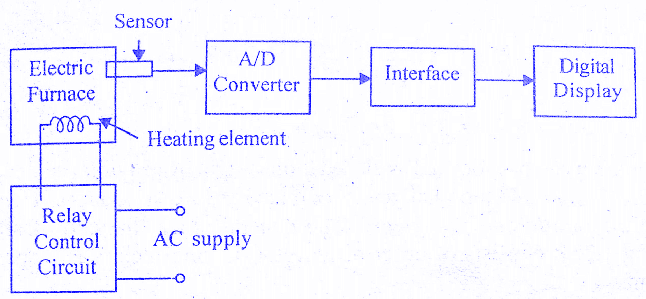
The temperature is measured by a sensor, which gives art analog voltage corresponding to the temperature of the furnace. The analog signal is converted to a digital signal by an Analog-digital converter (AD converter). The digital signal is given to the digital display device to display the temperature. In this open-loop system, if there is any change in output temperature then the time setting of the relay is not altered automatically.
Closed-Loop System Example:
The electric furnace shown in the below figure is a closed-loop system example. The output of the closed-loop system is the desired temperature and it depends on the time during which the supply to the heater remains ON.
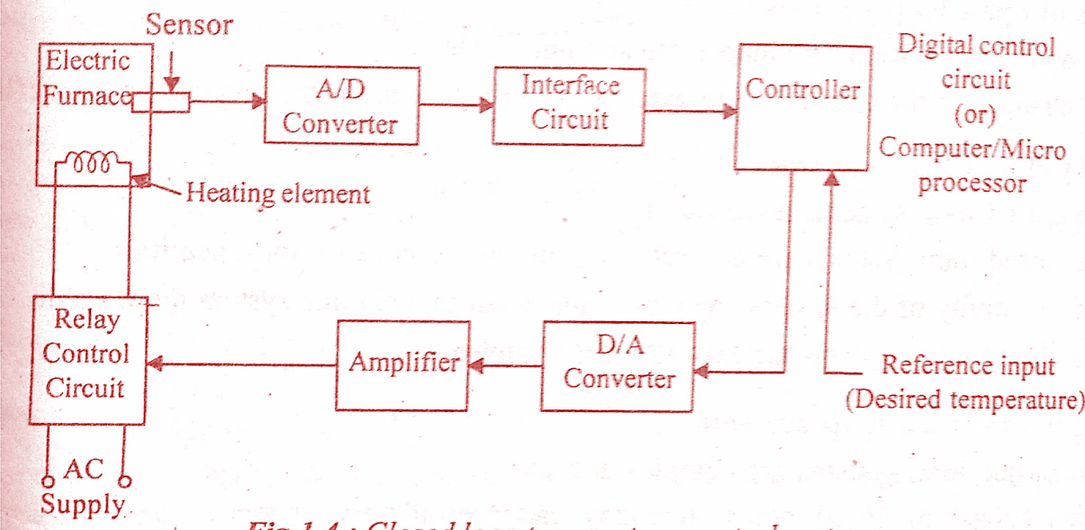
The switching ON and OFF of the relay is controlled by a controller which is a digital system or computer. The desired temperature is input to the system through the keyboard or as a signal corresponding to the desired temperature via ports. The actual temperature is sensed by the Sensor and converted to a digital signal by the A/D converter.
The computer reads the actual temperature and compares it with the desired temperature. If it finds any difference then it sends the signal to switch ON or OFF the relay through D/A converter and amplifier. Thus the system automatically corrects any changes in output. Hence it is a closed-loop system.
Example 2: Traffic Control System
Open Loop System example:
Traffic control by means of traffic signals operated on a time basis constitutes an open-loop control system. The sequence of control signals is based on a time slot given for each signal. The time slots are decided based on a traffic study. The system will not measure the density of the traffic before giving the signals. Since the time slot does not change according to traffic density, the system is an open-loop system.
Closed-Loop System Example:
A traffic control system can be made as a closed-loop system if the time slots of the signals are decided based on the density of traffic. In a closed-loop traffic control system, the density of the traffic is measured on all the sides and the information is fed to a computer. The timings of the control signals are decided by the computer based on the density of traffic Since the closed-loop system dynamically changes the timings, the flow of vehicles will be better than the open-loop system.
Example 3: Numerical Control System
Open Loop System:
Numerical control is a method of controlling the motion of machine components using numbers. Here, the position of the work head tool is controlled by the binary information contained in a disk. A magnetic disk is prepared in a binary form representing the desired part P (P is the metal part to be machined). The tool will operate on the desired part P. To start the open-loop system, the disk is fed through the reader to the D/A converter.
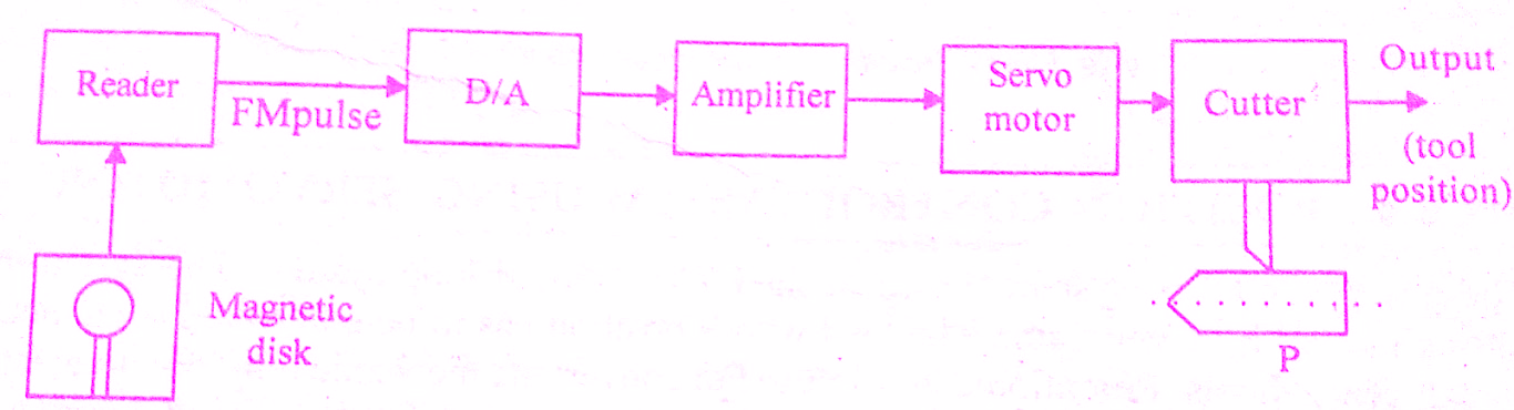
The D/A converter converts the FM(frequency modulated) output of the reader to a analogue signal. It is amplified and fed to a servomotor which positions the cutter on the desired part P. The position of the cutter head is controlled by the angular motion of the servomotor.
This is an open-loop system example since no feedback path exists between the output and input. The system positions the tool for a given input command. Any deviation in the desired position is not checked and corrected automatically.
Closed-Loop System Example:
A magnetic disk is prepared in a binary form representing the desired part P (P is the metal part to be machined). To start the closed-loop system, the disk is loaded into the reader. The controller compares the frequency modulated input pulse signal with the feedback pulse signal. The controller is a computer or microprocessor system.
The controller carries out mathematical operations on the difference in the pulse signals and generates an error signal. The D/A converter converts the controller output pulse (error signal) into an analog signal. The amplified analog signal rotates the servomotor to position the tool on the job.
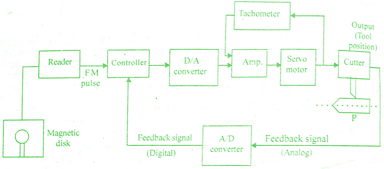
The position of the cutter head is controlled according to the input of the servomotor. The transducer attached to the cutter head converts the motion into an electrical signal. The analog electrical signal is converted to the digital pulse signal by the A/D converter. Then this signal is compared with the input pulse signal.
If there is any difference between these two, the controller sends a signal to the servomotor to reduce it. Thus the closed-loop system automatically corrects any deviation in the desired output tool position. An advantage of numerical control is that complex parts can be produced with uniform tolerances at the maximum milling speed.
Example 4: Position Control System Using Servomotor
The position control system shown below is a closed-loop system example. The system consists of a Servomotor powered by a generator. The load whose position has to be controlled is connected to the motor shaft through gear wheels. Potentiometers are used to convert mechanical motion to electrical signals. The desired load position (θR) is set on the input potentiometer and the actual load position (θc) is fed to the feedback potentiometer.
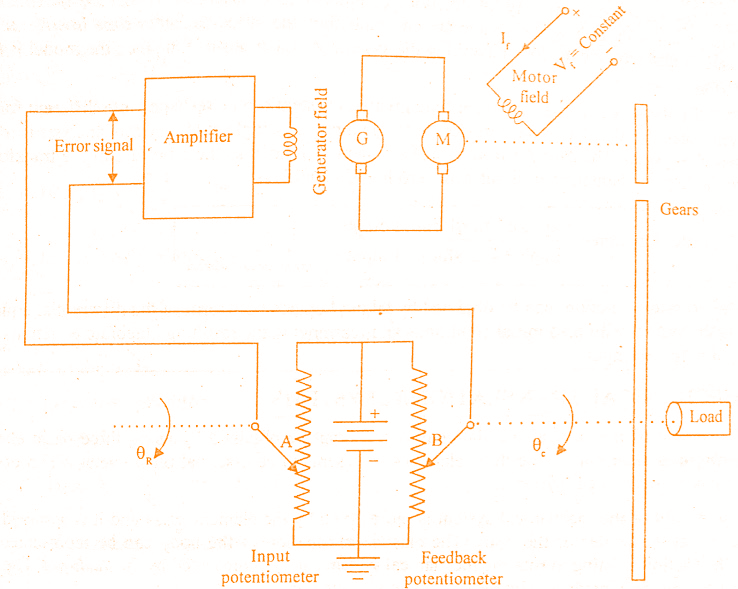
The difference between the two angular positions generates an error signal which is amplified and fed to the generator field circuit. The induced emf of the generator drives the motor. The rotation of the motor stops when the error signal is zero, i.e. when the desired load position is reached.
This type of control system is called servomechanisms. The servo or servomechanisms are feedback control systems in which the output is the mechanical position (or time derivatives of position e.g. velocity and acceleration).
Conclusion:
Today we have learned Open & Closed Loop Control System Examples. Please comment below for any queries.