Ideal Transformer:
Now we have already discussed much Transformers and types of transformers.Now we are going to know how the transformer is its ideal condition that is about the ideal transformer.
Ideal Transformer Definition:
A transformer which has no losses like eddy current losses, hysteresis losses, copper losses, frictional losses and other types of losses.The efficiency of an Ideal Transformer will be 100%.It can be simply spelt as loss less transformer.
Earlier it is seen that a voltage is induced in a coil when the flux linkage associated with the same changed.If one can generate a time varying magnetic field any coil placed in the field of influence linking the same experiences an induced emf.A time varying field can be created by passing an alternating current through an electric coil.This is called mutual induction.The medium can even be air.Such an arrangement is called an air core transformer.Indeed such arrangements are used in very high-frequency transformers.Even though the principle of transformer action is not changed, the medium has considerable influence on the working of such devices.These effects can be summarized as the followings.
Must Read:
1. The magnetizing current required to establish the field is very large, as the reluctance of the medium is very high.
2. There is a linear relationship between the MMF created and the flux produced.
3. The medium is non-lossy and hence no power is wasted in the medium.
4. A substantial amount of leakage flux exists.
5. It is very hard to direct the flux lines as we desire, as the whole medium is homogeneous.
If the secondary is not loaded the energy stored in the magnetic field finds its way back to the source as the flux collapses.If the secondary winding is connected to a load then part of the power from the source is delivered to the load through the magnetic field as a link.The medium does not absorb and lose any energy.
Power is required to create the field and not to maintain the same.As the winding losses can be made very small by proper choice of material, the ideal efficiency of a transformer approaches 100%.The large magnetizing current requirement is a major deterrent.However, if now a piece of magnetic material is introduced to form the magnetic circuit Figure(b) the situation changes dramatically.These can be enumerated as below.
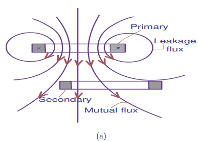 |
| Mutual Induction in air core |
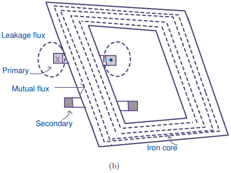 |
| mutual Induction in the iron core |
1.Due to the large value for the permeance (µr of the order of 1000 as compared to air) the magnetizing current requirement decreases dramatically. This can also be visualized as a dramatic increase in the flux produced for a given value of magnetizing current.
2.The magnetic medium is linear for low values of induction and exhibits saturation type of non-linearity at higher flux densities.
3.The iron also has hysteresis type of non-linearity due to which certain amount of power is lost in the iron (in the form of hysteresis loss), as the B-H characteristic is traversed.
4.Most of the flux lines are confined to the iron path and hence the mutual flux is increased very much and leakage flux is greatly reduced.
5.The flux can be easily ‘directed’ as it takes the path through steel which gives great freedom for the designer in the physical arrangement of the excitation and output windings.
6.As the medium is made of a conducting material eddy currents are induced in the same and produces losses. These are called ‘eddy current losses’. To minimize the eddy current losses the steel core is required to be in the form of a stack of insulated laminations.
From the above, it is seen that the introduction of the magnetic core to carry the flux introduced two more losses.Fortunately, the losses due to hysteresis and eddy current for the available grades of steel is very small at power frequencies.Also, the copper losses in the winding due to magnetization current is reduced to an almost insignificant fraction of the full load losses. Hence steel core is used in power transformers.
In order to have a better understanding of the behaviour of the transformer, initially certain idealizations are made and the resulting ideal transformer is studied.These idealizations are as follows:
1. Magnetic circuit is linear and has infinite permeability.The consequence is that a vanishingly small current is enough to establish the given flux. Hysteresis loss is negligible.As all the flux generated confines itself to the iron, there is no leakage flux.
2. Windings do not have resistance.This means that there are no copper losses, nor there is any ohmic drop in the electric circuit.
Must Read:
In fact, the practical transformers are very close to this model and hence no major departure is made in making these assumptions.The figure below shows a two winding ideal transformer.The primary winding has T1 turns and is connected to a voltage source of V1 volts.The secondary has T2 turns.The secondary can be connected to a load impedance for loading the transformer.The primary and secondary are shown on the same limb and separately for clarity.The below figure shows ideal transformer phasor diagram.
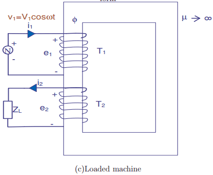
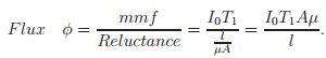
As a current I0 amp is passed through the primary winding of T1 turns it sets up an mmf of I0T1 ampere which is, in turn, sets up a flux φ through the core.Since the reluctance of the iron path given by R = l/µA is zero as µ → ∞, a vanishingly small value of current I0 is enough to setup a flux which is finite. As I0 establishes the field inside the transformer it is called the magnetizing current of the transformer.
This current is the result of a sinusoidal voltage V applied to the primary.As the current through the loop is zero (or vanishingly small), at every instant of time, the sum of the voltages must be zero inside the same. Writing this in terms of instantaneous values we have,
v1 – e1 = 0
where v1 is the instantaneous value of the applied voltage and e1 is the induced emf due to Faraday’s principle.The negative sign is due to the application of the Lenz’s law and shows that it is in the form of a voltage drop.Kirchoff’s law applied to the loop will result in the same thing.This equation results in v1 = e1 or the induced emf must be same in magnitude to the applied voltage at every instant of time.
Let v1 = V1peak cos ωt where V1peak is the peak value and ω = 2πft. f is the frequency of the supply.The following are the ideal transformer equations derived from observations.
As v1 = e1;
e1 = dψ1/dt but
e1 = E1peak cos ωt
∴ E1 = V1
It can be easily seen that the variation of flux linkages can be obtained as ψ1 = ψ1peak sin ωt. Here ψ1 peak is the peak value of the flux linkages of the primary.
Thus the RMS primary induced emf is
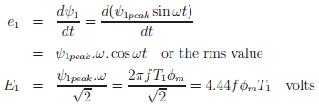
Here ψ1peak is the peak value of the flux linkages of the primary.The same mutual flux links the secondary winding.However, the magnitude of the flux linkages will be ψ2peak = T2 φm.The induced emf in the secondary can be similarly obtained as,
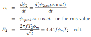
which yields the voltage ratio as

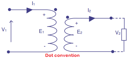
The voltages E1 and E2 are obtained by the same mutual flux and hence they are in phase.If the winding sense is opposite i.e. if the primary is wound in the clockwise sense and the secondary counter clockwise sense then if the top terminal of the first winding is at the maximum potential the bottom terminal of the second winding would be at the peak potential.A similar problem arises even when the sense of winding is kept the same, but the two windings are on opposite limbs (due to the change in the direction of flux).
Hence in the circuit representation of Transformers a dot convention(Figure below)is adopted to indicate the terminals of the windings that go high (or low) together.This can be established experimentally by means of a polarity test on the transformers.At a particular instant of time if the current enters the terminal marked with a dot it magnetizes the core.Similarly, a current leaving the terminal with a dot demagnetizes the core.
So far, an unloaded ideal transformer is considered.If now a load impedance ZL is connected across the terminals of the secondary winding a load current flows as marked in Figure(c) above.This load current produces a demagnetizing MMF and the flux tends to collapse.However, this is detected by the primary immediately as both E2 and E1 tend to collapse.The current drawn from supply increases up to a point the flux in the core is restored back to its original value.The demagnetizing MMF produced by the secondary is neutralized by additional magnetizing MMF produces by the primary leaving the mmf and flux in the core as in the case of no-load.Thus the transformer operates under constant induced emf mode.Thus,
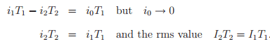
If the reference directions for the two currents are chosen as in the Figure above, then the above equation can be written in phasor form as,
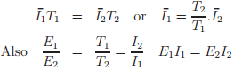
Thus voltage and current transformation ratio are inverses of one another.If an impedance of ZL is connected across the secondary,
![]()
The input impedance under such conditions is
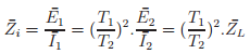
For study porpose