Understanding Self-Inductance:
Before we delve into Owen’s Bridge, it’s essential to have a solid grasp of the concept of self-inductance. When a current flows through a conductor, a magnetic field is created around it. If the current through the conductor changes, the magnetic field also changes, resulting in the induction of an EMF in the same conductor. This phenomenon is known as self-induction, and it’s quantified by a parameter called self-inductance (L), measured in henrys (H). Mathematically, the induced EMF (ε) is proportional to the rate of change of current (di/dt) and the self-inductance:
ε = -L * (di/dt)
Self-inductance is influenced by various factors, including the number of turns in the coil, the geometry of the coil, and the medium surrounding it. To accurately determine self-inductance, engineers and physicists employ techniques such as the Owen’s Bridge.
Owen’s Bridge: An Overview
Owen’s Bridge, named after its inventor E.R. Owen, is a specialized bridge circuit used for the measurement of self-inductance. The bridge operates on the principle of nullifying the voltage across a balanced circuit, which is achieved by adjusting various components of the circuit. This balance condition yields valuable information about the self-inductance of a coil or conductor.
Components of Owen’s Bridge
- Coil under Test (CuT): This is the coil for which the self-inductance needs to be measured.
- Variable Standard Inductor (L): A variable standard inductor is connected in series with the coil under test. Its inductance can be precisely adjusted and is used to achieve balance in the bridge circuit.
- Variable Resistance (R): A variable resistor is connected in parallel to the variable standard inductor. It plays a crucial role in balancing the bridge.
- Fixed Resistor (Rf): This resistor is connected in series with the variable standard inductor. Its value is known and contributes to balancing the bridge.
- Galvanometer (G): The galvanometer is connected across the bridge’s diagonal points. It detects the current flowing through the bridge circuit.
- AC Power Source (V): The alternating current power source provides the necessary input to the bridge circuit.
Balancing the Bridge:
The primary objective of using Owen’s Bridge is to achieve a balanced condition where the galvanometer shows zero deflection. When the bridge is balanced, the voltage across the diagonal points is minimal, indicating that the circuit is in equilibrium. Achieving this balance requires adjusting the values of the variable standard inductor (L) and the variable resistance (R).
The bridge is balanced when the ratio of the self-inductance of the coil under test (L_cuT) to the self-inductance of the variable standard inductor (L) is equal to the ratio of the fixed resistor (Rf) to the variable resistance (R):
L_cuT / L = Rf / R
Measuring Self-Inductance:
To measure the self-inductance of the coil under test, the following steps are generally followed:
- Initialization: Begin by setting the variable standard inductor (L) to a known value and the variable resistance (R) to a high value.
- Power Supply: Connect the AC power source to the circuit and allow the current to flow through it.
- Balancing the Bridge: Adjust the variable standard inductor (L) and the variable resistance (R) until the galvanometer shows zero deflection. This indicates that the bridge circuit is balanced.
- Calculating Self-Inductance: Once the bridge is balanced, note the values of L, R, and Rf. With these values, calculate the self-inductance of the coil under test (L_cuT) using the balanced bridge equation: L_cuT = L * (Rf / R)
Owen’s Bridge offers several advantages for measuring self-inductance:
- Accuracy: The bridge circuit provides a highly accurate method for determining self-inductance.
- Flexibility: The ability to adjust the variable standard inductor and resistance allows for precise balancing.
- Calibration: By using a known standard inductor and resistor, the bridge can be calibrated for more accurate measurements.
However, Owen’s Bridge also has some limitations:
- Complexity: Setting up and balancing the bridge can be complex and time-consuming.
- Sensitivity to Environmental Factors: External electromagnetic interference or fluctuations in the power source can affect the bridge’s accuracy.
- Applicability: Owen’s Bridge is best suited for measuring self-inductance in relatively low-frequency applications.
Owen’s bridge may be used for the measurement of inductance in terms of capacitance. The below figure shows the connections and phasor diagrams, for Owen’s bridge, under balance conditions.
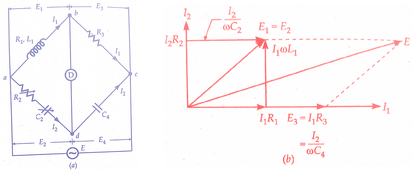 |
| Measurement of Self Inductance by Owen’s Bridge |
Let
L1 = unknown self-inductance of resistance
R2 = variable non-inductive resistance,
R3 = fixed non-inductive resistance,
C2 = variable standard capacitor,
C4 = fixed standard capacitor
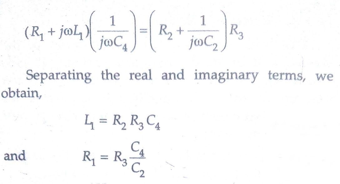
At balance,
Advantages of Owen’s Bridge:
- Examining the equations for balance, We find that we obtain two independent equations in case C2 and R2 are made variable. Since R2 and C2, the variable elements, are in the same arm, convergence to balance conditions is much easier.
- The balance equations are quite simple and do not contain any frequency component.
- Owen’s Bridge can be used over a wide range of measurement of inductances.
Also Read:
Disadvantages of Owen’s Bridge:
- Owen’s bridge requires a variable capacitor which is an expensive item and also its accuracy is about 1 per cent.
- The value of capacitance C2 tends to become rather large when measuring high Q coils.
Conclusion:
Self-inductance is a crucial parameter in the study of electromagnetism and electrical circuits. Accurate measurement of self-inductance is essential for designing and analyzing various electronic devices. Owen’s Bridge, a specialized bridge circuit, provides a reliable method for determining self-inductance by achieving a balanced condition in the circuit. Although setting up the bridge can be intricate, its accuracy and precision make it a valuable tool in the field of electrical engineering. By mastering the principles of Owen’s Bridge and self-inductance, engineers and researchers can contribute to the advancement of technology and our understanding of electromagnetism.
In this, we have learnt the measurement of Self Inductance by Owen’s Bridge. You can download this article as pdf, ppt.
Share and comment below!