The Basics of Self-Inductance
Before delving into the intricacies of Hay’s Bridge, let’s grasp the basics of self-inductance. When current flowing through a coil changes, a magnetic field is generated around it. This changing magnetic field induces a voltage across the coil, which opposes the change in current according to Faraday’s law of electromagnetic induction. Mathematically, this relationship is represented as:
V = -L[di/dt]
Where:
- (V) is the induced voltage (EMF)
- (L) is the self-inductance of the coil
- (di/dt) is the rate of change of current
Self-inductance is usually measured in units of henries (H), where 1 henry is equivalent to 1 volt-second per ampere 1H = 1V *(s/A)
Understanding Hay’s Bridge
The Hay’s Bridge is a four-arm bridge circuit primarily used to measure the self-inductance of a coil. It is an adaptation of the Wheatstone bridge and operates based on the principle of null detection. The bridge comprises four arms, each consisting of resistors and inductors. The arrangement allows for comparing the unknown self-inductance with a known reference inductance.
The basic configuration of the Hay’s Bridge includes three components:
- The unknown self-inductance coil (Lx)
- A known reference inductance (Ls)
- A variable resistor (R)
The bridge is balanced when the ratio of the self-inductance to the reference inductance is equal to the ratio of the resistances in the arms of the bridge:
Lx/Ls = R1/R2
Working Principle
The Hay’s Bridge works on the concept of a balanced bridge, where the voltage across the detector (usually a galvanometer) becomes zero. The bridge is balanced by adjusting the variable resistor until this zero voltage condition is achieved. At balance, the unknown self-inductance can be calculated using the formula:
Lx = Ls (R1/R2)
Here, (R1) and (R2) represent the resistances in the arms of the bridge.
Advantages and Limitations
The Hay’s Bridge offers several advantages in measuring self-inductance:
- Accuracy: When properly calibrated and adjusted, the Hay’s Bridge provides accurate measurements of self-inductance.
- Relative Measurements: The bridge allows for relative measurements, comparing the unknown inductance to a known reference.
- Minimal External Factors: It is less affected by external factors like temperature variations and power supply fluctuations.
However, the Hay’s Bridge also has some limitations:
- Manual Balancing: Achieving balance manually can be time-consuming and may require careful adjustment.
- Sensitivity to Frequency: The bridge’s performance can be affected by the frequency of the AC source used.
- Complexity: Constructing and setting up the bridge requires precision in resistor and inductor values.
Practical Implementation
To implement the Hay’s Bridge for measuring self-inductance, follow these steps:
- Circuit Setup: Connect the components in the bridge circuit – self-inductance coil, reference inductance, and variable resistor. The bridge configuration forms a closed loop.
- AC Source: Connect an AC source to the bridge circuit to provide alternating current.
- Galvanometer: Connect a sensitive galvanometer to the detector points of the bridge.
- Initial Balancing: Initially, set the variable resistor to a mid-point and adjust it until the galvanometer shows zero deflection. This indicates that the bridge is close to being balanced.
- Fine Balancing: Make fine adjustments to the variable resistor until the galvanometer shows no deflection, achieving a balanced state.
- Measurement: Once balanced, note the values of the reference inductance (Ls) and the resistance ratio (R1/R2).
- Calculations: Calculate the unknown self-inductance (Lx) using the formula mentioned earlier: Lx = Ls (R1/R2)
Conclusion:
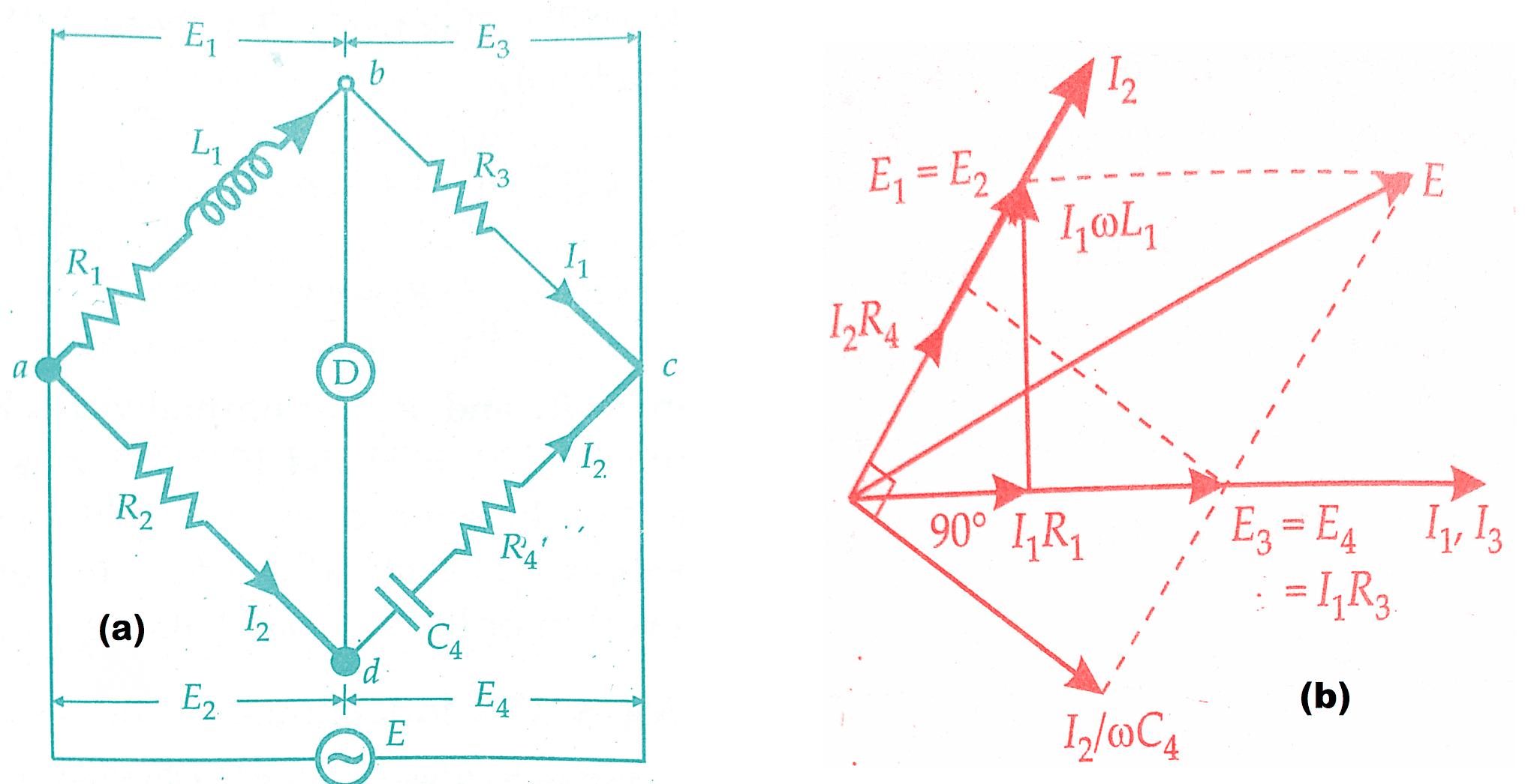
The Hay’s bridge is a modification of Maxwell’s bridge. The connection diagram and the phasor diagram for Hay’s Bridge are shown in the below figure. Hay’s bridge uses resistance in series with the standard capacitor (unlike Maxwell’s bridge which uses resistance in parallel with the capacitor).
Let L1 = unknown inductance having a resistance R1
R2, R3, R4 = known non-inductive resistance,
and C4 = standard capacitor.
 |
| Measurement of Self Inductance By Hay’s Bridge |
Must Read:
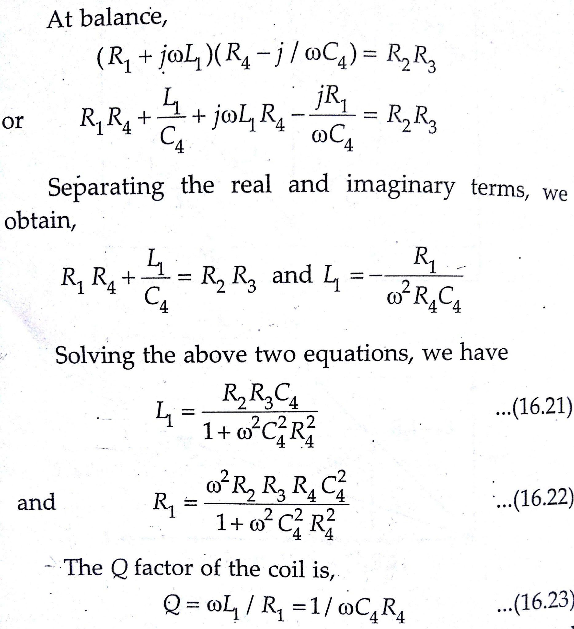
The expressions for the unknown inductance and resistance contain the frequency term. Therefore it appears that the frequency of the source of supply to the bridge must be accurately known. This is not true for the inductance when a high Q coil is being measured as is explained below:
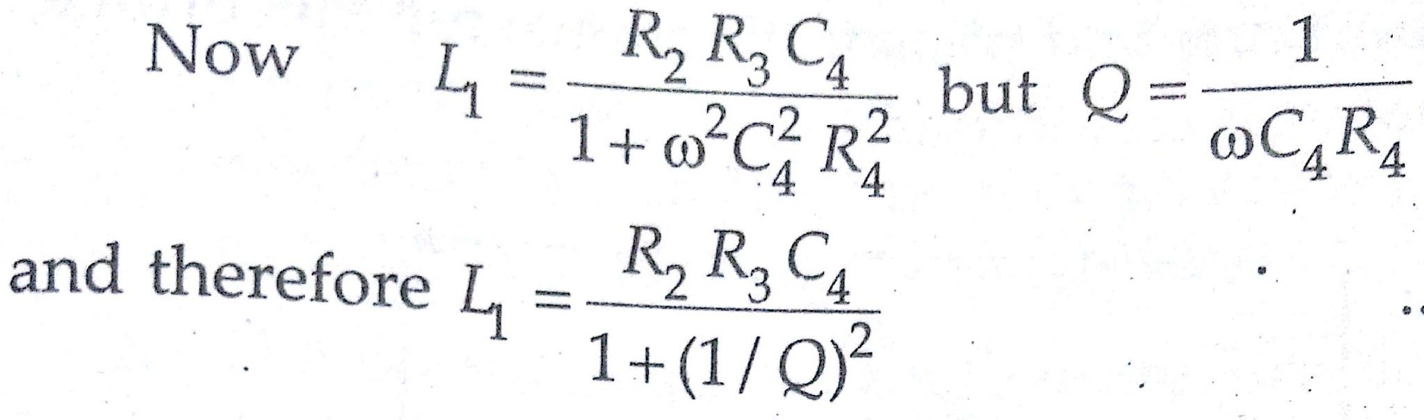
For a value of Q greater than 10, the term (1/Q)² will be smaller than 1/100 and can be neglected.
Therefore the above equation reduces to
L1 = R2 R3 C4
which is the same as for Maxwell’s bridge.
Advantages of Hay’s Bridge:
- Hay’s bridge gives a very simple expression for unknown inductance for high Q coils and is suitable for coils having Q > 10.
- Hay’s bridge also gives a simple expression for Q factor.
- If we examine the expression for Q factor
Q = 1/ωC₄R₄
We find that the resistance R4 appears in the denominator and hence for high Q coils its value should be small. Thus Hay’s bridge requires only a low-value resistor for R4, whereas Maxwell’s bridge requires a parallel resistor, R4, of very high value.
Disadvantages of Hay’s Bridge:
- The Hay’s bridge is suited for the measurement of high Q inductors, especially those inductors having a Q greater than 10.
- For inductors having Q values smaller than 10, the term (1/Q)² in the expression for inductance L1 becomes rather important and thus cannot be neglected.
- Hence Hay’s bridge is not suited for measurement of coils having Q less than 10 and for these applications Maxwell’s bridge is more suited.
Conclusion:
The measurement of self-inductance by Hay’s Bridge is a valuable technique in the field of electrical engineering. It offers an effective method to determine the self-inductance of coils and helps engineers and researchers design and optimize circuits involving inductive components. Despite its limitations, the Hay’s Bridge remains an essential tool for accurate inductance measurements, contributing to advancements in various technological domains.
In this, we have learnt Measurement of Self Inductance By Hay’s Bridge. You can download this article as pdf, ppt.
Comment below for any Queries.
i like it👍