Integrating Type Digital Voltmeter(DVM):
As we have already discussed what is working of digital voltmeter and its types, now we will discuss the second type DVM i.e, integrating type digital voltmeter. This digital voltmeter measures the true average value of the input voltage over a fixed measuring period. In contrast, the ramp type DVM samples the voltage at the end of the measuring period.
This voltmeter employs an integration technique whirls uses a voltage to frequency conversion. The voltage to frequency (V/F) converter functions as a feedback control system which governs the rate of pulse generation in proportion to the magnitude of input voltage.
Actually, when we employ the voltage to frequency conversion techniques, a train of pulses, whose frequency depends upon the voltage being measured, is generated. Then the number of pulses appearing in a definite interval of time is counted. Since the frequency of these pulses is a function of unknown voltage, the number of pulses counted in that period of time is an indication of the input (unknown) voltage.
The heart of this technique is the operational amplifier acting as an Integrator.
Output voltage of integrator Eo = – Ei (1/RC) t
Thus if a constant input voltage Ei is applied, an output voltage Eo is produced which rises at a uniform rate and has a polarity opposite to that input voltage. In other words, it is clear from the above relationship, that for a constant input voltage the integrator produces a ramp output voltage of opposite polarity.
This textbook “Electrical and Electronics Measurements by S. Chand” is the best in industry. Grab it now for very less price.
Must Read:
Let us examine the below figure. Here the graphs are showing the relationship between input voltages of three different values and their respective output voltages are shown. It is clear that the polarity of the output voltage is opposite to that of the input voltage. Not only that, the greater the input voltage the sharper is the rate of rise or slope of the output voltage.
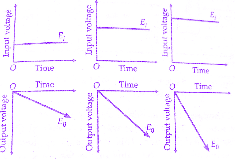 |
| Graphs of output voltages for different input voltages of Integrating type digital voltmeter(DVM) |
Integrating Type Digital Voltmeter(DVM) Block Diagram:
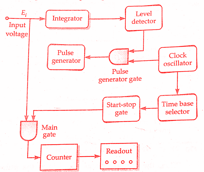 |
| Block diagram of integrating type digital voltmeter(DVM) |
The basic block diagram of a typical integrating type digital voltmeter(DVM) is shown in the above figure. Here is the working principle of Integrating type digital voltmeter(DVM). The unknown voltage is applied to the input of the integrator, an output voltage(Eo) starts to rise. The slope of the output voltage (Eo) is determined by the value of input voltage (Ei). This voltage is fed a level detector and when Eo reaches a certain reference level, the detector sends a pulse to the pulse generator gate.
Integrating Type Digital Voltmeter(DVM) Working Principle:
The level detector is a device similar to a voltage comparator. The output voltage from integrator (Eo) is compared with the fixed voltage of an internal reference source, and, when Eo reaches that level, the detector produces an output pulse. It is evident that greater the value of input voltage Ei the sharper will be the slope of output voltage Eo, and quicker the output voltage Eo will reach its reference level.
The output pulse of the level detector opens the pulse generation gate, permitting pulses from a fixed frequency clock oscillator to pass through the pulse generator. This generator is a device such as a Schmitt trigger, that produces an output pulse of fixed amplitude and width for every pulse it receives.
This textbook “Electrical and Electronics Measurements by S. Chand” is the best in industry. Grab it now for very less price.
This output pulse, whose polarity is opposite to that of Ei and has a greater amplitude, is feedback to the input of the integrator. Hence, the net input to the integrator is now of a reversed polarity (opposite to that of Ei as is clear from the below figure). As a result of this reversed input, the output Eo drops back to its original level. Since Eo is now below the reference level of the level detector, there is no output from the detector to the pulse generator gate and the gate gets closed. Thus no more pulses from the clock oscillator can pass through to trigger the pulse generator.
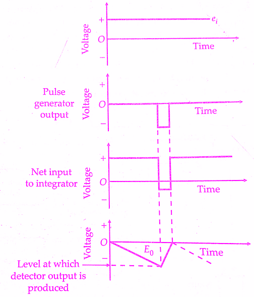 |
| Output voltage waveform in integrating type digital voltmeter(DVM) |
When the output voltage pulse from the pulse generator has passed, Ei is restored to its original value and Eo starts its rise again. When it reaches the level of reference voltage again, the pulse generator gate is opened. The pulse generator is triggered by a pulse from the clock generator and the entire cycle is repeated again. Thus, the waveform of Eo is a sawtooth wave whose rise time is dependent upon the value of input voltage E, and the fall time is determined by the width of the output pulse from the pulse generator.
Thus the frequency of the sawtooth wave (Eo) is a function of the value of Ei, the voltage being measured. Since one pulse from the pulse generator is produced for each cycle of the sawtooth wave, the number of pulses produced in a given time interval and hence the frequency of the sawtooth wave is an indication of the value of voltage being measured.
The frequency of sawtooth wave may be measured by counting the number of pulses in a given interval of time. Pulses from the clock oscillator are applied to a time base selector. The first pulse passes through the start-stop gate, producing an output which is applied to the main gate, thus opening the gate. As a result of this, the same output pulses from the pulse generator (that are applied to integrator) also pass through the main gate.
The next pulse from the time base closes the start-stop gate and also the main gate.Thus no more pulse generator pulses can pass through.Hence the counters and their associated readout indicate the number of pulses that have passed during a known interval of time.This count is an indication of the voltage being measured. In order to make the counter read directly in terms of voltage, the amplitude and width of pulse generator pulses can be suitably adjusted.
Must Read:
Conclusion:
Now here we have discussed integrating type digital voltmeter(DVM) working principle and block diagram. You can download this article as pdf, ppt.
Comment below for any Queries.