Potentiometric type digital voltmeter(DVM):
In the previous posts we have already discussed working of digital voltmeter and its types, now we will discuss Potentiometric type digital voltmeter. A potentiometric type of digital voltmeter employs voltage comparison technique. In this DVM the unknown voltage is compared with a reference voltage whose value is fixed by the setting of the calibrated potentiometer.
The potentiometer setting is changed to obtain balance (i.e., null conditions).When null conditions are obtained, the value of the unknown voltage is indicated by the dial setting of the potentiometer. In potentiometric type DVMs , the balance is not obtained manually but is arrived at automatically. Thus, this DVM is, in fact, a self-balancing potentiometer. The potentiometric DVM is provided with a readout which displays the voltage being measured.
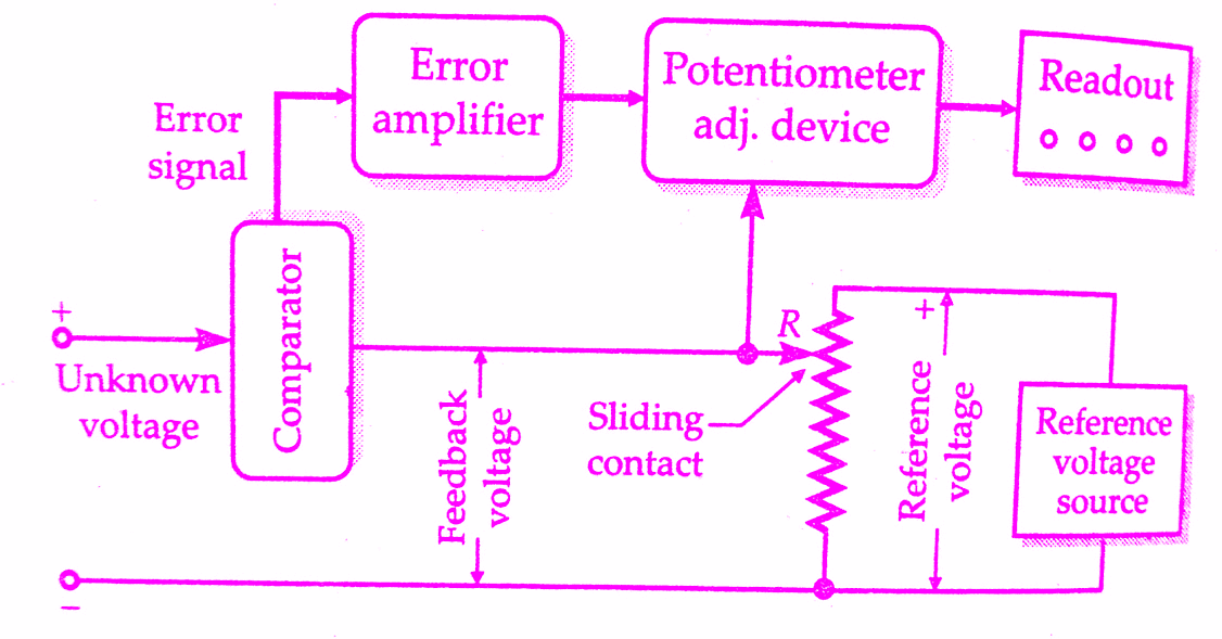
Block diagram of Potentiometric type digital voltmeter(DVM):
The block diagram of the basic circuit of a potentiometric DVM is shown in the below figure.
Working principle of Potentiometric type digital voltmeter:
The unknown voltage is filtered and attenuated to a suitable level. This input voltage is applied to a comparator (also known as error detector). This error detector may be chopper. The reference voltage is obtained from a fixed voltage source. This voltage is applied to a potentiometric R. The value of the feedback voltage depends upon the position of the sliding contact. The feedback voltage is also applied to the comparator.
The unknown voltage and the feedback are compared in the comparator. The output voltage of the comparator is the difference of the above two voltages. The difference of voltage is called the error signal. The error signal is amplified and is fed to a potentiometer adjustment device which moves the sliding contact of the potentiometer. This magnitude by which the sliding contact moves depends upon the magnitude of the error signal.
The direction of movement of slider depends upon whether the feedback voltage is larger or the input voltage is larger. The sliding contact moves to such a place where the feedback voltage equals the unknown voltage. In that case, there will not be any error voltage and hence there will be no input to the device adjusting the position of the sliding, contact and therefore it (sliding contact) will come to rest.
The position of the potentiometer adjustment device at this point is indicated in numerical form on the digital readout device associated with it. Since the position at which no voltage appears at potentiometer adjustment device is the one where the unknown voltage equals the feedback voltage, the reading of readout device indicates the value of unknown voltage.
The potentiometer adjustment device i.e., the device which moves the sliding contact is a 2 phase servo motor.The automatic action of adjustment of sliding contact with the help of a servomotor has already been explained in chapter 12. The reference voltage source must be extremely stable and generally consists of a standard cell or Zener diode sources.
Practical potentiometric digital voltmeter(DVM):
A practical potentiometric DVM does not consist of a single resistor R but consists of a number of decade resistors connected in the Kelvin Varley slide fashion. The below figure shows a practical potentiometric digital voltmeter circuit. A stepping switch operates the variable voltage divider, which is composed of wire wound resistors and divides the reference voltage into a number of precisely equal parts in a decimal number system.
This circuit has four resistance decades and therefore converts the input (unknown) analog voltage to a 4-digit decimal number. There are four stepping switches (which may be called decade switches).
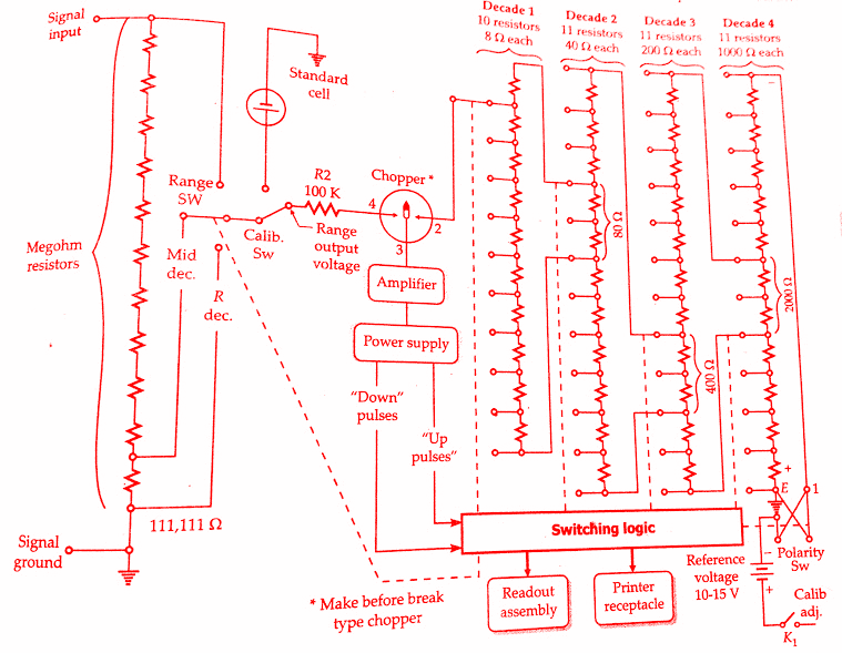
An error amplifier compares the feedback voltage with the input signal and commands stepping switches to move until they come to a position where the two voltages are within the limits of resolution of the instrument. At this point, the stepping switch motion stops and the readout indicates the value of the input (unknown) voltage.
Conclusion:
Now here we have discussed potentiometric type digital voltmeter(DVM) working principle and block diagram.You can download this article as pdf, ppt.
Comment below for any Queries.