What is Ramp Type Digital Voltmeter?
As we discussed already, the working principle of the basic digital voltmeter(DVM), now we will discuss one of its types Ramp type digital voltmeter. Digital voltmeter is an electrical measuring instrument used to display the potential difference between two points in the form of digits.
Ramp Type Digital Voltmeter(DVM) Block diagram:
 |
| Block diagram of digital voltmeter |
Must Read:
Ramp Type Digital Voltmeter(DVM) Working Principle:
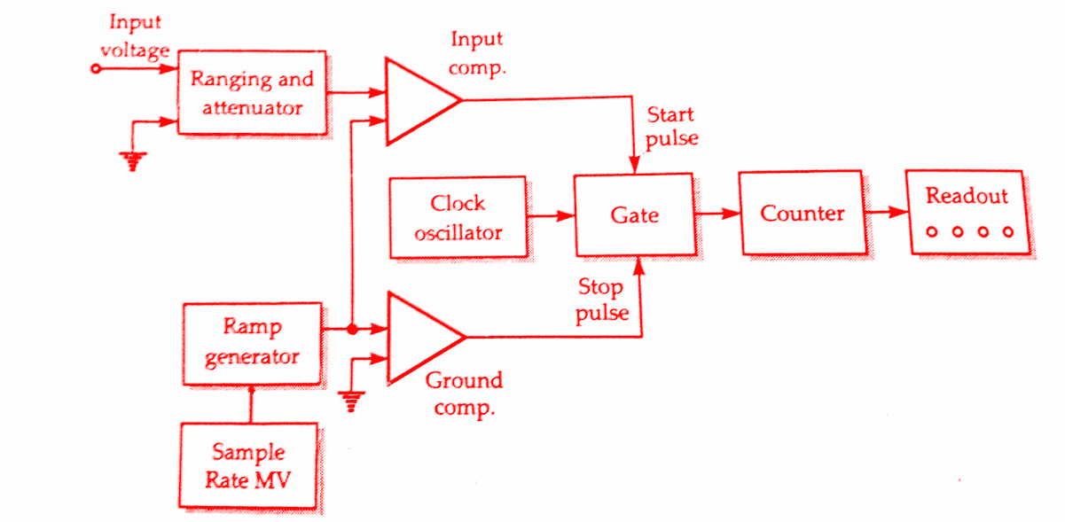
The block diagram shown above is ramp type digital voltmeter(DVM). You can see there is a ramp generator. This is generating a waveform which is representing a ramp. The heart of the circuit is the ramp generator. Therefore it is called ramp type digital voltmeter(DVM).
The input which should be measured is given at input voltage. This input is fed to ranging and attenuator circuit which will amplify the signal if it is small or attenuates the signal if it is large.
This textbook “Electrical and Electronics Measurements by S. Chand” is the best in industry. Grab it now for very less price.
This is given to an input comparator which will compare two signals and generates the output. One input to the input comparator is from the input voltage and another input is from the ramp. This input voltage and ramp signal are compared and output is given.
If the ramp signal is more than input voltage there will be no output but if the input voltage is greater than the ramp signal then a is generated which will open the gate. Now when the gate gets opened, clock oscillator will send clock pulses which are counted by the counter and displayed on the screen.
The ground comparator will compare the ramp signal and ground and output is given. This output will stop the flow of purchase from clock oscillator by closing the gate. The sample rate multivibrator is used to reset the ramp generator. The operating principle of ramp type digital voltmeter is to measure the time that a linear ramp voltage takes to change from the level of the input voltage to zero voltage (or vice versa). This time interval is measured with an electronic time interval counter and the count is displayed as a number of digits on electronic indicating tubes of the output readout of the voltmeter.
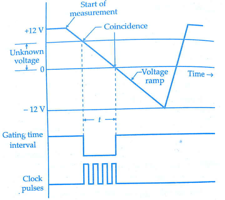
The conversion of a voltage value of a time interval is shown in the below timing diagram. At the start of measurement, a ramp voltage is initiated. A negative going ramp is shown in the below figure but a positive going ramp may also be used. The ramp voltage value is continuously compared with the voltage being measured (unknown voltage). At the instant, the value of ramp voltage is equal to that of unknown voltage a coincidence circuit, called an input comparator, generates a pulse which opens a gate (see above block diagram).
The ramp voltage continues to decrease till it reaches ground level (zero voltage). At this instant, another comparator called ground comparator generates a pulse and closes the gate. The time elapsed between the opening and closing of the gate is t as indicated in the below timing diagram of ramp type digital voltmeter. During this time interval pulses from a clock pulse generator pass through the gate and are counted and displayed.
Must Read:
Timing diagram of ramp type digital voltmeter(DVM):
 |
| Timing diagram of ramp type digital voltmeter(dvm) |
The decimal number as indicated by the readout is a measure of the value of input voltage. The sample rate multivibrator determines the rate at which the measurement cycles are initiated. The sample rate circuit provides an initiating pulse for the ramp generator to start its next ramp voltage. At the same time, it sends a pulse to the counters which set all of them to 0.This momentarily removes the digital display of the readout.
Conclusion:
Now here we have discussed working principle and block diagram explanation of ramp type digital voltmeter (DVM’s). You can download this as pdf, ppt.
Comment below for any Queries.
this is very amazing, but please give proteus simulation for ramp type digital voltmeter please please
Thank you for your comment! I’m glad you found the article amazing