Construction of Reluctance Motor:
We know about different types of synchronous motors, apart from all these motor works based on reluctance. So it is called Reluctance Motor. Here we will discuss construction and working principle of Reluctance Motor. The reluctance motor has basically two main parts called stator and rotor. the stator has a laminated construction, made up of stampings.
The stampings are slotted on its periphery to carry the winding called stator winding. The stator carries only one winding. This is excited by single-phase a.c. supply. The laminated construction keeps iron losses to a minimum. The stampings are made up of material from silicon steel which minimises the hysteresis loss. The stator winding is wound for certain definite number of poles.
The rotor has a particular shape. Due to its shape, the air gap between stator and rotor is not uniform.No d.c supply is given to the rotor. The rotor is free to rotate. The reluctance i.e., the resistance of the magnetic circuit depends on the air gap. More the air gap, more is the reluctance and vice-versa. Due to the variable air gap between stator and rotor, when the rotor rotates, reluctance between stator and rotor also changes. The stator and rotor are designed in such a manner that the variation of the inductance of the windings is sinusoidal with respect to the rotor position.
Must Read:
The construction of Reluctance Motor is shown in figure(a) while the practical rotor of Reluctance Motor is shown in figure(b) below.
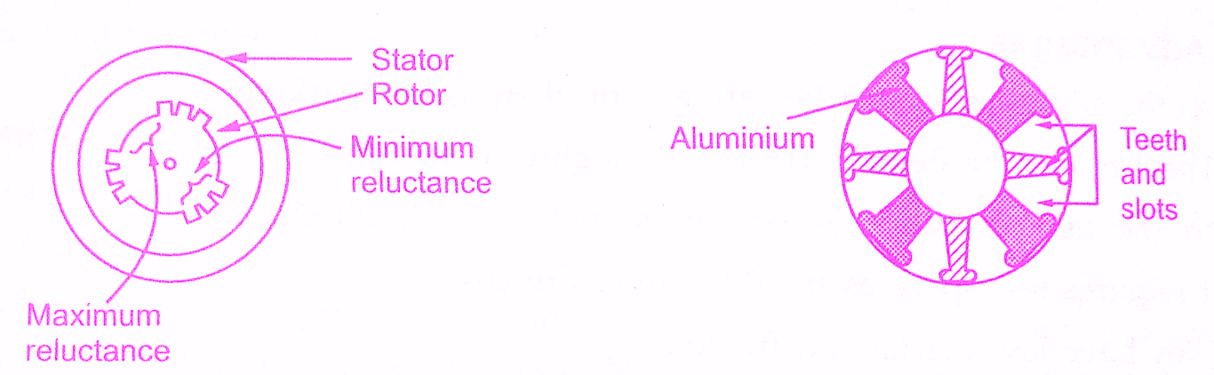 |
| Construction of reluctance motor |
Working Principle of Reluctance Motor:
The stator consists of a Single Winding called main winding. But single winding cannot produce rotating magnetic field. So for production of rotating magnetic field, there must be at least two windings separated by the certain phase angle. Hence stator consists of an additional winding called auxiliary winding which consists of a capacitor in series with it.
Thus there exists a phase difference between the currents carried by the two windings and corresponding fluxes. Such two fluxes react to produce the rotating magnetic field. The technique is called split phase technique of production of the rotating magnetic field. The speed of this field is the synchronous speed which is decided by the number of poles for which stator winding is wound.
This textbook “Electrical Machinery by P.S. Bhimbhra” is the best in industry. Grab it now for very less price.

The rotor carries the short-circuited copper or aluminium bars and it acts as a squirrel-cage rotor of an induction motor. If an iron piece is placed in a magnetic field, it aligns itself in a minimum reluctance position and gets locked magnetically. Similarly, in the reluctance motor, rotor tries to align itself with the axis of rotating magnetic field in a minimum reluctance position. But due to rotor inertia, it is not possible when the rotor is standstill.
So rotor starts rotating near synchronous speed as a squirrel cage induction motor. When the rotor speed is about synchronous, stator magnetic field pulls rotor into synchronism i.e. minimum reluctance position and keeps it magnetically locked. Then rotor continues to rotate with a speed equal to synchronous speed. Such a torque exerted on the rotor is called the reluctance torque. Thus finally the reluctance motor runs as a synchronous motor. The resistance of the rotor must be very shall and the combined inertia of the rotor and the load should be small to run the motor as a synchronous motor.
Torque equation of Reluctance Motor:
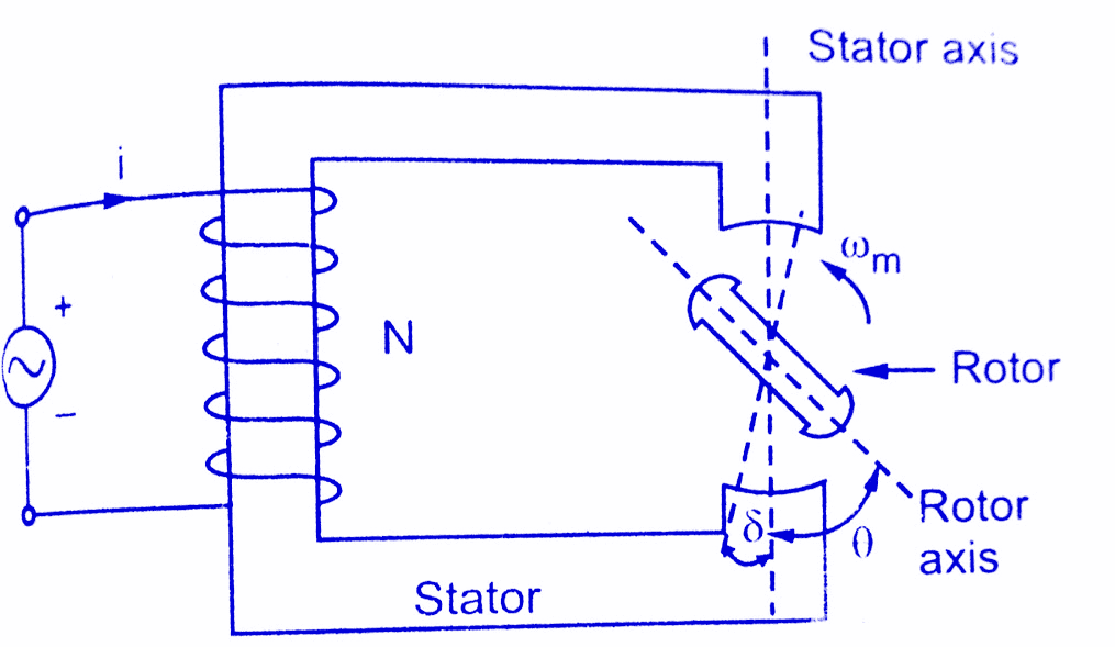 |
| Elementary reluctance motor |
Consider an elementary reluctance motor as shown in the figure.The variation of the inductance of the windings is sinusoidal with respect to rotor position.The variation of the inductance with respect to θ is of double frequency and is given by,
L(θ) = L′′ + L′ Cos 2θ
The stator winding is excited by a.c supply hence
i = Im Sin ωt
The energy stored is a function of Inductance and given by,
W = 1/2 L(θ) i²
The flux linkage is given by,
λ(θ) = L(θ) i
Then the torque is given by
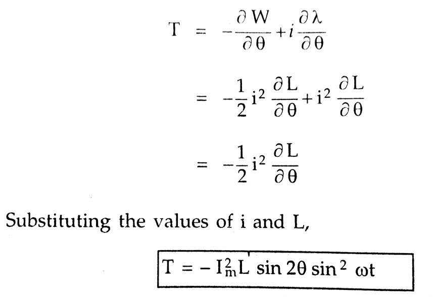
If the rotor is rotating at an angular velocity ωm then finally the torque equation can be expressed in terms of ω and ωm as,
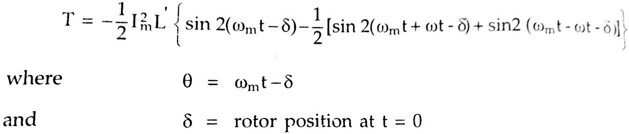
The above equation gives instantaneous torque produced. The average torque is zero as the average of each term in the above equation is zero. The value of torque is not zero when ω = ωm at this condition the magnitude of the average torque is,
![]()
The speed corresponding to the frequency ω = ωm is nothing but the synchronous speed. The δ is a torque angle. The maximum torque occurs at δ = 45° which is termed as pull-out torque.
Key Point: Any load demanding torque more than pull-out torque pulls the motor out of synchronism.
Torque – speed characteristics of Reluctance Motor:
The torque speed characteristics are shown in below figure. The starting torque is highly dependent on the position of the rotor.
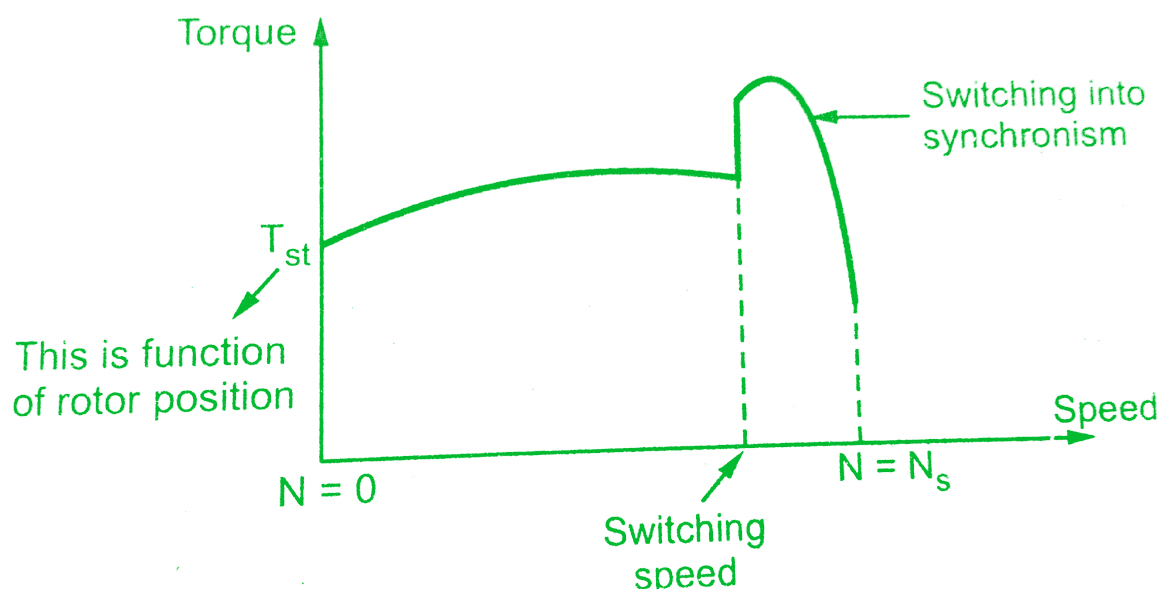 |
| Torque speed characteristics of reluctance motor |
Reluctance Motor Advantages:
The reluctance motor has the following advantages,
1) No d.c. supply is necessary for the rotor.
2) Constant speed characteristics.
3) Robust construction.
4) Less maintenance.
Reluctance Motor Disadvantages:
The reluctance motor has following limitations,
1) Less efficiency
2) Poor power factor
3) Need of very low inertia rotor
4) Less capacity to drive the loads
Also Read:
Applications of Reluctance Motor:
Reluctance motor is used in
- Signalling Devices
- Control Apparatus
- Automatic regulators
- Recording Instruments
- Clocks
- All timing devices
- Teleprinters
- Gramophones
Conclusion:
Now we have learnt construction and Working principle of Reluctance Motor and its applications. You can download this article as pdf, ppt.
Comment below for any Queries.