Laboratory-type or DC Crompton’s Potentiometer:
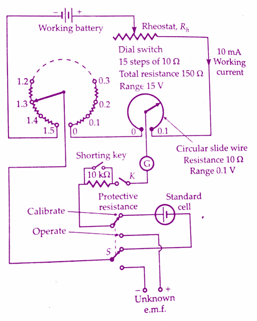
The slide-wire type of potentiometer described in the previous article is not a practical form of construction. The long slide wire is awkward, and even for the length shown cannot be read to a very great degree of precision. Modern laboratory type potentiometers use calibrated dial resistors and a small circular wire of one or more turns, thereby reducing the size of the instrument. The circuit of a simple DC Crompton’s potentiometer theory is shown in the below figure. There is one dial switch with fifteen steps, each having a precision resistor. There is also a single turn circular slide wire.
For the case shown, the resistance of slide wire is 10 Ω and the dial resistors have a value of 10 Ω each. Thus the dial has a total resistance of 150 Ω and in addition, the slide wire has a resistance of 10 Ω. The working current of the potentiometer is 10 mA and therefore each step of dial switch corresponds to 0.1 V.
The slide wire is provided with 200 scale divisions and since the total resistance of slide wire corresponds to a voltage drop of 0.1 V, each division of slide wire corresponds to 0.1/200 = 0.0005 V. It is quite comfortable to interpolate readings upto 1/5 of a scale division and therefore with this potentiometer it is possible to estimate the readings upto 0.0001 V.
This textbook “Electrical and Electronics Measurements by S. Chand” is the best in industry. Grab it now for very less price.
Must Read:
 |
| Laboratory-type potentiometer |
This potentiometer is provided with a double throw switch which allows the connection of either the standard cell or the unknown emf to be applied to the working circuit. A key and a protective resistance (usually about 10 KΩ) is used in the galvanometer circuit. In order to operate the galvanometer at its maximum sensitivity provision is made to short the protective resistance when near the balance conditions.
The following steps are used when making measurements with the above potentiometer:
1. The combination of dial resistors and the slide wire is set to the standard cell voltage. Supposing the value of emf of the standard cell is 1.0186 V, the dial resistors put at 1.0 V and the slide wire is put at 0.0186 setting.
2. The switch S is thrown to the calibrate position and the galvanometer key is tapped while the rheostat is adjusted for zero deflection on the galvanometer. The protective resistance is kept in the circuit in the initial stages so as to protect the galvanometer from being getting damaged.
3. As the balance or null point is approached, the protective resistance is shorted so as to increase the sensitivity of the galvanometer. Final adjustments are made for zero deflection with the help of the rheostat. This completes the standardisation process for the potentiometer.
4. After completion of standardisation, the switch ‘S’ is thrown to operate position thereby connecting the unknown emf into the potentiometer circuit. With the protective resistance in the circuit, the potentiometer is balanced by means of the main dial and the slide wire.
5. As the balance is approached, the protective resistance is shorted, and final adjustments are made to obtain true balance.
6. The value of unknown emf is read off directly from the settings of the dial adjust slide wire.
7. The standardisation of the potentiometer is checked again by returning the switch S to the calibrate position. The dial settings are kept exactly the same as in the original standardisation process. If the new reading does not agree with the old one, the second measurement of unknown emf must be made. The standardisation should be again checked after the completion of the measurement. This potentiometer is a form of DC Crompton’s Potentiometer.
Multiple Range Potentiometer :
The single-range potentiometer shown above is frequently constructed to cover a range of 1.6 V – though, of course, it can be designed for any desired voltage within reasonable and practical limits. For example, a DC Crompton’s potentiometer is designed to measure voltages up to 1.9 V by simply adding three more resistance steps to the main dial.
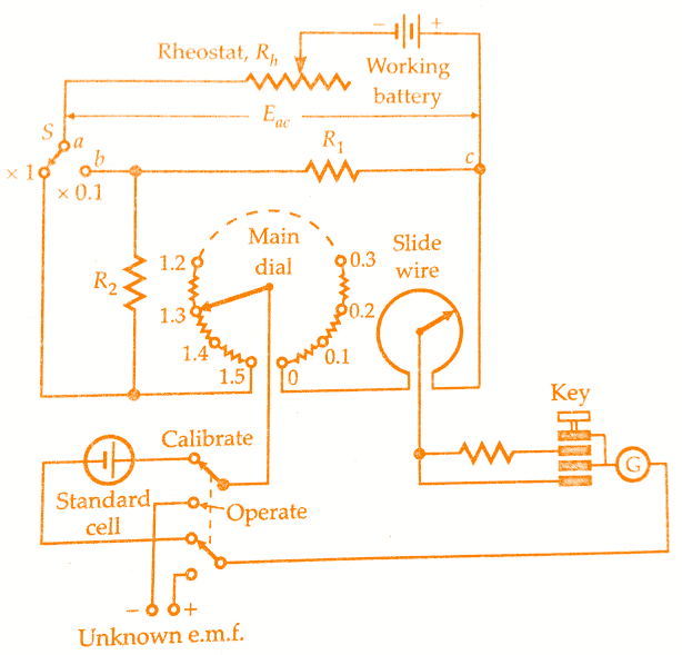
The circuit of a single potentiometer may be modified in a simple way to add a second range, which is usually by a second factor, such as 0.1 or 0.01, in order that the direct reading features of the original circuit may still be utilised.
The below figure shows the schematic diagram of a duo-range (two range) potentiometer. The two ranges are obtained by using two resistors R1 and R2 and a range selecting switch S.The operation of the duo range potentiometer may be more easily understood and analysed by redrawing in its simplified form by omitting the galvanometer and calibration (standardising) circuit. The simplified diagram is shown below.
 |
| Duo range type potentiometer |
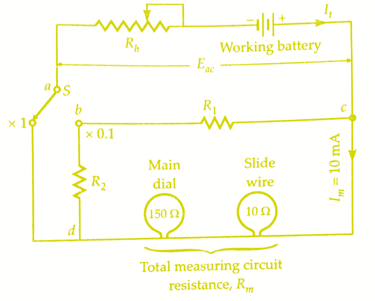
In the above figure, the total resistance of measuring of the circuit, Rm consists of resistance of the main dial in series with that of slide wire. The main dial has fifteen steps of 10 Ω each and therefore it has a total resistance of 150Ω. The resistance of slide wire is 10 Ω. The measuring circuit current Im must be equal to 10 mA in order to produce a voltage drop of 1.6 V across the measuring circuit resistance Rm i.e., the resistance of the main dial and the slide wire in series.
The diagrams above and below, with the range switch S in x 1 position, represent an identical arrangement as shown in the first figure. When the range switch S is thrown to position x 0.1, the measuring current Im must be reduced to 1/10 of its original value i.e., 1 mA in order to produce a voltage drop of 0.16 V across the measuring circuit resistance Rm.
 |
| duo range potentiometer |
The design of circuit of a duo-range potentiometer should be such that it is possible to change the measuring ranges without re-adjusting the rheostat or changing the value of working voltage of the battery. This is essential so that once the instrument has been calibrated on x 1 range, calibration of the x 0.1 range is not necessary. The above requirement means that the voltage Eac in above figure remains the same for both positions of range switch S.This condition is satisfied only when the total battery current has the same value for each measuring range.
Precision Type Potentiometers:
The potentiometers described so far are simple instruments capable of a precision of 100 µV for readings up to 1.6 V.These difficulties to get accurate results mainly arise because of lack of uniformity of slide wire and the difficulties in maintaining the contacts in good shape. However, for some applications higher precision and accuracy are needed, requiring changes in design features. Some of the features are explained below:
Vernier Potentiometers:
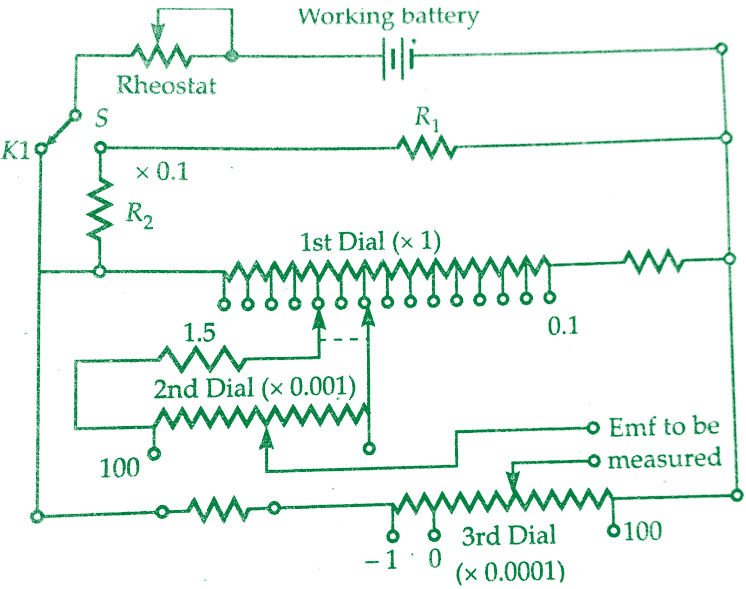
The limitations imposed on the performance of ordinary potentiometers by slide wire are eliminated in a vernier potentiometer. This instrument has two ranges: the normal range of 1.6V down to 10 µV and a lower range of 0.16 V down to 1 µV.
This potentiometer uses the Kelvin Varley arrangement shown below. However, in this potentiometer, there are three measuring dials. The first dial measures upto 1.5 V (on the XI range) in steps 0.1 V : the middle dial has 102 studs and reads upto 0.1 V in steps of 0.001 V; the third dial also has 102 studs and reads from – 0.0001 V to 0.001 V in steps of 0.00001 V (i.e., 10 µV).There is no slide wire. The resistances of the middle dial shunt two of the coils of the first dial.
The moving arm of middle dial carries two arms spaced two studs apart. In actual practice the resistance of the second dial is greater than that between two studs in the main (first) dial, so that the voltage drop across the second dial is greater than 0.1 V.If this is not done the voltage drop in switch contact resistances and leads would render the converge of middle dial to less than 0.1 V. The third dial is obtained from a shunt circuit which permits a true zero and a small negative setting to be obtained.
 |
| duo range vernier potentiometer |
The vernier potentiometer reads to the increment of 0.00001 V (10 µV) on range XI and has the readability of 1 µV on x 0.1 range. If a third range of x 0.01 is provided, the readability becomes 0.1 µV. This does not mean, unfortunately, that small voltages can be read with assurance to 0.1 µV. Measurements are subject to stray thermal and contact EMFs in the potentiometer, galvanometer and the measuring circuits.
These EMFs may be of the order of one to several microvolts and are difficult to locate and control. These EMFs can be minimised only by special construction i.e., proper selection of metals for resistors, terminals and connecting leads and also by the use of thermal shields.
Standard Cell Dial Potentiometer:
All modern potentiometers incorporate a separate standard cell dial circuit (calibrating circuit). This provides a means of standard cell balance resistance to suit the emf value of the particular standard cell used. Also, a separate standard cell dial permits the operator to check the standard cell balance at any time during the course of measurement without disturbing the potentiometer setting.
The figure below shows a separate standard cell dial incorporated in a single range potentiometer. This potentiometer is provided with an independent standardising circuit AD which can be set on any range of standard cell emf from 1.016 V to 1.020 V.A drop of 1.016 V is provided by resistance Rs and the remaining drop of 0.004 V is provided by the slide wire AC. Thus a considerable change in standard cell emf owing to temperature changes can be allowed for the operation of the circuit below.
The slide wire of the calibrating circuit is set to read the emf of the standard cell which is connected to the potentiometer. The selector switch S is put in the calibrate position and the rheostat is adjusted so that there is no current flowing through the galvanometer. This fixes the working current to its proper value. The switch S is then thrown to the operate position and unknown emf is read by adjusting the measuring circuit dial and slide wire.
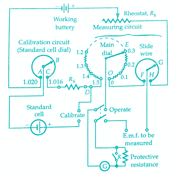 |
| Single range potentiometer using independent calibrating circuit |
The standardising circuit may be checked for the constancy of working current, anytime during the measurements by simply throwing the switch S back to calibrate position. This process does not disturb the measuring circuit while convenience and speed of measurements are increased.
This textbook “Electrical and Electronics Measurements by S. Chand” is the best in industry. Grab it now for very less price.
Must Read:
Brooks Deflectional Potentiometer:
Brooks deflectional potentiometer is used for applications where the voltage to be measured is continuously changing, with a conventional type of potentiometers, it becomes impossible to obtain exact balance even when the changes are slow since it is difficult to follow the changes by manipulation of the dials. The figure below shows a deflectional potentiometer. In this potentiometer, only one or two main dials, consisting of decade resistance boxes, are used. A centre zero type galvanometer is included in the circuit to indicate deflection.
The galvanometer circuit includes a set of compensating resistors R1, R2. The value of the compensating resistors is such that the resistance of the potentiometer circuit, as viewed from terminals, where the unknown emf is applied, remains constant irrespective of the position of the sliding contacts. This means that current through the galvanometer will always be proportional to the out of balance current whatever may be the setting of the main dials.
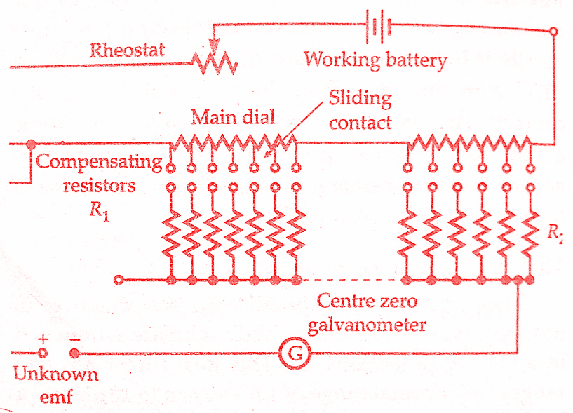 |
| Brooks deflectional potentiometer |
Thus the galvanometer scale can be calibrated to read the out of balance emf directly. The value of the unknown emf is obtained by adding the galvanometer reading to the main dial setting. The main dial setting is kept nearly equal to the emf being measured.
The potentiometer is used to monitor the value of temperature where a thermocouple is employed. The output of the thermocouple is fed to the unknown emf terminals. Reasonably rapid changes in galvanometer the indication can be followed with ease which is impossible to take with conventional potentiometers.
Conclusion:
Now here we have discussed different types of DC potentiometers like Laboratory type or Crompton’s, Brooks deflectional, Standard Cell Dial, Vernier, Precision type, Multiple Range potentiometers. You can download this article as pdf, ppt.
Comment below for any Queries.