Synchronous Generator or Alternator:
It is known that the electric supply used now-a-days for commercial, as well as domestic purposes, is of alternating type.Similar to d.c machines, the a.c machines associated with alternating voltages, are also classified as generators and motors.
Machines generating ac EMF are called alternators or synchronous generators. While the machines accepting input from a.c supply to produce a mechanical output are called synchronous motors.Both these machines work at a specific constant speed called synchronous speed and hence is general called synchronous machines.
Difference between DC Generator and Alternator:
It is seen that in the case of a d.c generator, basically, the nature of the induced e.m.f in the armature conductors is of alternating type. By using commutator and brush assembly it is converted to d.c and made available to the external circuit.
If commutator is dropped from a d.c generator and induced e.m.f is tapped from an armature directly outside, the nature of such emf will be alternating. Such a machine without a commutator, providing an a.c emf to the external circuit is called an alternator.
This textbook “Electrical Machinery by P.S. Bhimbhra” is the best in industry. Grab it now for very less price.

Construction of Synchronous generator or alternator:
In Synchronous generator or alternators the stationary winding is called ‘stator’ while the rotating winding is called ‘Rotor’.
Stator:
The stator in the synchronous generator is a stationary armature.This consists of a core and the slots to hold the armature winding similar to the armature of a d.c generator.The stator core uses a laminated construction.It is built up of special steel stampings insulated from each other with varnish or paper.The laminated construction is basically to keep down eddy current losses.
Generally choice of material is steel to keep down hysteresis losses.The entire core is fabricated in a frame made of steel plates.The core has slots on its periphery for housing the armature conductors.The frame does not carry any flux and serves as the support to the core.Ventilation is maintained with the help of holes cast in the frame.
Rotor:
There are two types of rotors used in the synchronous generators or alternators:
1) Salient pole rotor
2)Smooth cylindrical rotor
1) Salient pole rotor:
This is also called projected pole type as all the poles are projected out from the surface of the rotor.The poles are built up of thick steel laminations.The poles are bolted to the rotor as shown in the figure.The pole face has been given a specific shape.The field winding is provided on the pole shoe.These rotors have large diameters and small axial lengths.
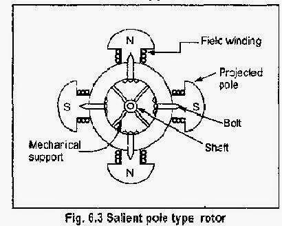
The limiting factor for the size of the rotor is the centrifugal force acting on the rotating member of the machine. As the mechanical strength of salient pole type is less, this is preferred for low-speed alternators ranging from 125 r.p.m to 50 r.p.m.The prime movers used to drive such rotor are generally water turbines and I.C. engines.
2)Smooth cylindrical rotor:
This is also called non-salient type or non-projected pole type or round rotor.This rotor consists of a smooth solid steel cylinder, having a number of slots to accommodate the field coil.These slots are covered at the top with the help of steel or manganese wedges.The unslotted portions of the cylinder itself act as the poles.The poles are not projecting out and the surface of the rotor is smooth which maintains a uniform air gap between stator and rotor.
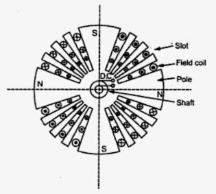
These rotors have small diameters and large axial lengths.This is to keep peripheral speed within limits.The main advantage of this type is that these are mechanically very strong and thus preferred for high-speed alternators ranging between 1500 to 3000 r.p.m. Such high-speed alternators are called ‘turbo-alternators’.The prime movers used to drive such type of rotors are generally steam turbines, electric motors.
Working Principle of Synchronous generator :
The alternators work on the principle of electromagnetic induction. When there is a relative motion between the conductors and the flux, emf gets induced in the conductors. The dc generators also work on the same principle. The only difference in the practical synchronous generator and a dc generator is that in an alternator the conductors are stationary and field is rotating. But for understanding, the purpose we can always consider relative motion of conductors w.r.t the flux produced by the field winding.
Consider a relative motion of a single conductor under the magnetic field produced by two stationary poles. The magnetic axis of two poles produced by field is vertical, shown dotted in below figure.
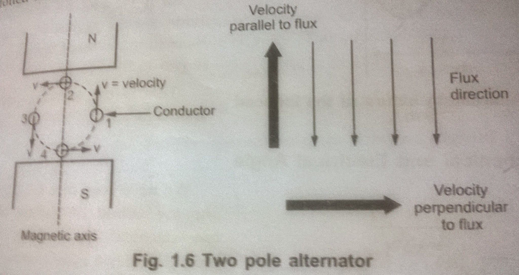
Let conductor starts rotating from position 1.at this instant, the entire velocity component is parallel to the flux lines. Hence there is no cutting of flux lines by the conductor. So d@/dt at this instant is zero and hence induced emf in the conductor is also zero. As the conductor moves from position 1 to position 2, the part of the velocity component becomes perpendicular to the flux lines and proportional to that, emf gets induced in the conductor. The magnitude of such an induced emf increases as conductor moves from position 1 to 2.
At position 2, the entire velocity component is perpendicular to the flux lines. Hence there exists cutting of the flux lines. And at this instant, the induced emf in the conductor is at its maximum. As the position of conductor changes from 2 to 3, the velocity component perpendicular to the flux starts decreasing and hence induced emf magnitude also starts decreasing.At position 3, again the entire velocity component is parallel to the flux lines and hence at this instant induced emf in the conductor is zero.
As the conductor moves from 3 to 4, velocity component perpendicular to the flux lines again starts increasing. But the direction of velocity component now is opposite to the direction of velocity component existing during the movement of the conductor from position 1 to 2.Hence an induced emf in the conductor increase but in the opposite direction.
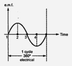
At position 4, it achieves maxima in the opposite direction, as the entire velocity component becomes perpendicular to flux lines. Again from position 4 to 1, induced emf decreases and finally at the position again becomes zero. This cycle continues as conductor rotates at a certain speed. So if we plot the magnitudes of the induced emf against the time, we get an alternating nature of the induced emf shown figure above. This is the working principle of Synchronous generator or Alternator.
Diesel powered generators, or electrical generator sets, are used in countless industrial and commercial establishments.
The generators can be used for small loads, such as in homes, as well as for larger loads like industrial plants,
hospitals, and commercial buildings.
Best Diesel Generator in chennai