Amplifiers in Cathode Ray Oscilloscope:
As we have already discussed cathode ray oscilloscope, we use two amplifiers in Cathode ray oscilloscope(CRO) for the formation of graphical presentation on CRT screen.The purpose of an oscilloscope is to give the accurate representation applied to its terminals at the input side, considerable attention has to be paid to the designing of these amplifiers for a faithful representation of input signals.The amplifiers used in oscilloscope can be classified into two types:
(i) a.c coupled amplifiers
(ii) d.c coupled amplifiers
This textbook “Electrical and Electronics Measurements by S. Chand” is the best in industry. Grab it now for very less price.
Must Read:
Low-cost oscilloscopes use a.c. coupled amplifiers. For laboratory purposes, A.C. amplifiers are commonly used in oscilloscopes. The d.c. coupled amplifiers are expensive, they offer the advantage of responding to d.c. voltages. Their use makes it possible to measure d.c. voltages, pure a.c. signals, and to measure a.c. signals superimposed upon d.c. signals.
DC coupled amplifiers have the additional advantage, that they eliminate the problem of low frequency’ phase shift and accompanying waveform problem of waveform distortion when observing low frequency pulse train.
There is another way of classifying oscilloscope amplifiers. They can be classified according to the bandwidth they use. On this basis, they can be classified as:
(i) narrow bandwidth amplifiers
(ii) broad bandwidth amplifiers.
These categories of amplifiers are not sharply divided, nor is the classification universally accepted. If the frequency band does not extend upto the television colour sub-carrier frequency of 3.58 MHz, the amplifier can be classified as the narrow band.
However, if the frequency response curve of the amplifier is flat beyond 3.58 MHz, the amplifier is classified as a broadband amplifier. Most general purpose, laboratory quality oscilloscopes respond fully to frequencies in excess of 5 MHz.Therefore, the responsible amplifier, which is the vertical amplifier, is broadband.
Must Read:
Verticle amplifier in CRO:
The vertical amplifier is the principal factor in determining the sensitivity and bandwidth of an oscilloscope. In general, greater sensitivity, which is expressed in terms of V/cm of vertical deflection at the midband frequency, is obtained at the expense of bandwidth.
As a rule of thumb, an amplifier at some specific cost may be obtained with a certain gain-bandwidth product, which is the product of the voltage gain of the amplifier and its bandwidth. Voltage gain may be sacrificed in favour of greater bandwidth, or vice versa, without significantly affecting the cost of the amplifier. However, if the gain-bandwidth product increases, the cost of the amplifier will increase.
The gain of the vertical amplifier determines the smallest signal that the oscilloscope can satisfactorily reproduce on the CRT screen. The sensitivity of an oscilloscope is directly proportional to the gain of the vertical amplifier that is, as gain increases sensitivity increases, which allows us to observe smaller amplitude signals.
The vertical sensitivity is a measure of how much the electron beam will be deflected for a specified input signal. The CRT screen is covered with a plastic grid pattern called a graticule. The spacing between the grid lines is generally 10 mm. However, vertical sensitivity is generally expressed in volt per division. On the front panel of the oscilloscope shown in the figure ‘block diagram of the horizontal amplifier of an oscilloscope‘, one can see a knob attached to a rotary switch labelled pin.
The gain could be designated V/Div. The rotary switch is electrically connected to the input attenuator network, which will be discussed in subsequent paragraphs. The setting of the rotary switch indicates what amplitude signal is required to deflect the beam vertically by one division.
The vertical sensitivity of an oscilloscope is the smallest deflection factor that can be selected with the rotary switch. As an example, if the most sensitive position on the volt/division rotary switch is 5 mV/division, then the vertical sensitivity of the oscilloscope is 5 mV/division. The bandwidth of an oscilloscope determines the range of frequencies that can be accurately reproduced on the CRT screen.
The greater the bandwidth, the wider is the range of frequencies that can be observed with the instrument. Ideally, the gain of the broadband amplifier should be constant from direct current to near the upper limit of the range of frequencies can be observed with the oscilloscope.
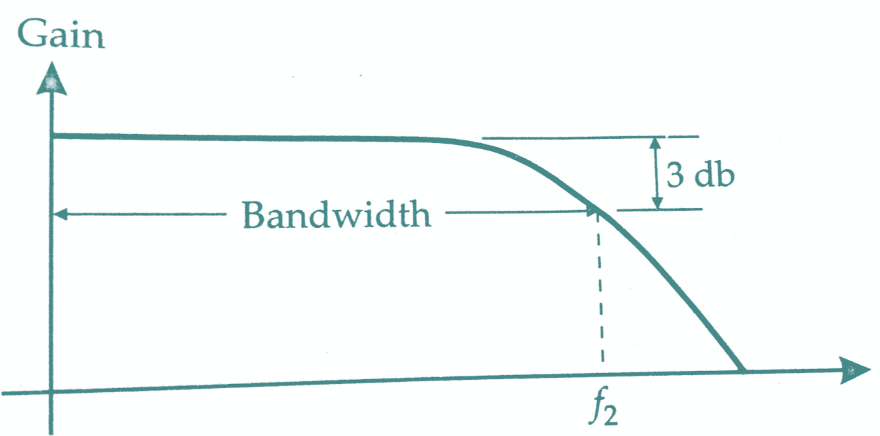
A typical curve for a broadband amplifier of gain versus frequency called a frequency-response curve is shown in the below figure. The bandwidth of an oscilloscope is the range of frequencies over which the gain of the vertical amplifier is within 3 dB of the midband frequency gain. The upper limit of the bandwidth is the frequency, f2, at which the gain has decreased by 3dB. The bandwidth can be increased by using feedback in designing the amplifier. However, this reduces the gain, which is why the gain-bandwidth product for an amplifier is constant.
One of the specifications generally included on the specifications sheet for the vertical amplifier of a broadband oscilloscope is the rise time. The rise time of a pulse is defined as the time required for the edge to rise from 10% to 90% of its maximum amplitude. When an oscilloscope is used to observe a pulse or a square wave, the rise time of the instrument must be faster than the rise time of the pulse or square wave, otherwise, the observed signal will not be accurately reproduced. Although the exact relationship between bandwidth and the rise time varies slightly with amplifier design, an approximate relationship is given as
tr x BW = 0.35
where tr = rise time measured in second,
BW = bandwidth in hertz.
The vertical amplifier of a laboratory quality oscilloscope frequently consists of the two major circuit blocks shown in the below figure, a pre-amplifier and the main vertical amplifier or mainframe amplifier.
The pre-amplifier is sometimes a separate, interchangeable plug-in unit that can quickly and easily be plugged into the mainframe of the oscilloscope. If different plug-in units are available for specific measurement applications, the measurement capabilities of an oscilloscope can be broadened considerably at a reasonable cost.
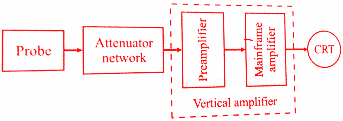
The active element in the first stage of the pre-amplifier is generally a field-effect transistor (FET) which provides a high input impedance for the oscilloscope.The final stage of the mainframe amplifier is generally a push-pull amplifier which provides voltages of equal amplitude but out of phase by 180° to achieve balanced deflection.
This textbook “Electrical and Electronics Measurements by S. Chand” is the best in industry. Grab it now for very less price.
Horizontal Amplifier in CRO:
The horizontal amplifier basically serves two purposes:
1. When the oscilloscope is being used in the ordinary mode of operation to display a signal applied to the vertical input, the horizontal amplifier will amplify the sweep generator output.
2. When the oscilloscope is being used in the X-Y mode, the signal applied to the horizontal input terminal will be amplified by the horizontal amplifier.
When the oscilloscope is being used in its ordinary mode of operation, the gain and bandwidth requirements for the horizontal amplifier are not as stringent as those for the vertical amplifier. Although the vertical amplifier must be able to reproduce faithfully low amplitude, high-frequency signals with fast rise times, the horizontal amplifier is required to provide only a faithful reproduction of the sweep signal, which has a relatively high amplitude and a slow rise time.
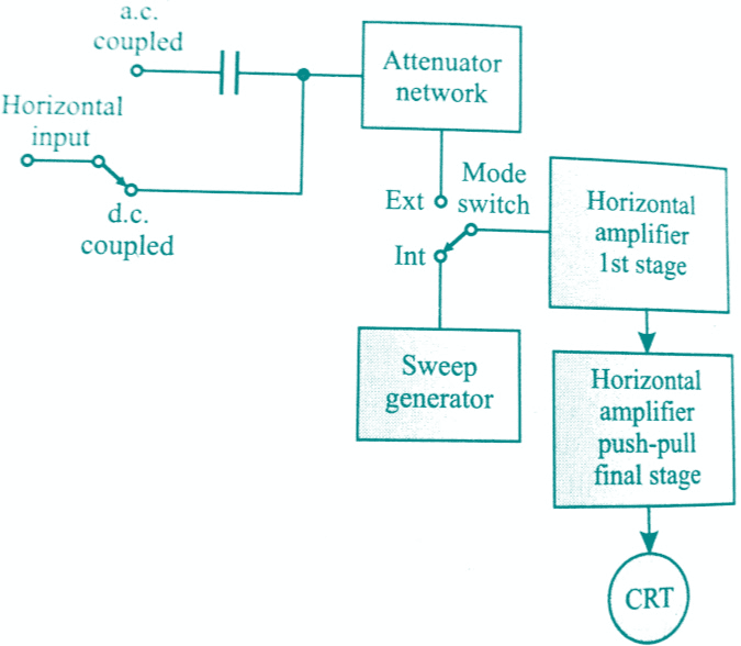
As with the vertical amplifier, the final stage of the horizontal amplifier is a push-pull amplifier, as shown in below figure. The attenuator network given in the figure reduces, by voltage division, the amplitude of the horizontal input signal to a level equal to the sensitivity of the horizontal amplifier.
Conclusion:
Now here we have discussed Vertical & Horizontal amplifiers in cathode ray oscilloscope. You can download this notes to your device in pdf, ppt format.
Comment below for any Queries.