Electrostatic Focusing in Cathode Ray Oscilloscope(CRO):
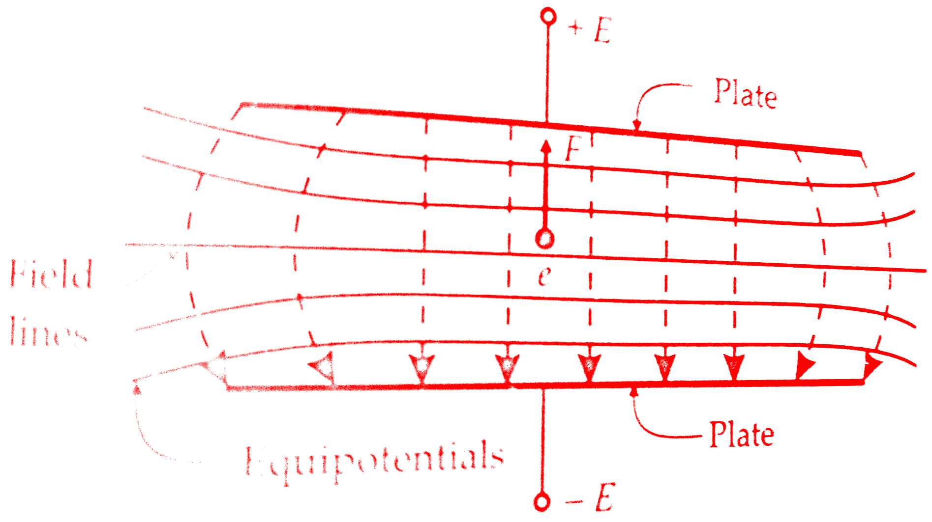
We have already discussed What is Cathode Ray Oscilloscope(CRO) ? and also types of deflection systems in Cathode Ray Oscilloscope(CRO).Now we will discuss the electrostatic focusing in Cathode Ray Oscilloscope tube.Initially, this electron starts from an electron gun.These series of electrons coming from electron gun will form a beam.The figure electric field between parallel plates shows an electron at rest placed in an electric field produced two parallel plates.
Force on the electron is,
F = -eε N
where ε = electric field intensity ; V/m
e = charge of electron = 1.602 ×10⁻¹⁹ C
The minus sign indicates that the force acts in the opposite direction to that of the field.The above discussion is valid only if the electron is situated in a field of uniform intensity.In practice, however, the field is not uniform.The lateral repulsion of the electric field lines causes a spreading of space between the lines, resulting in curved field lines at the ends.
Thus the field intensity will be less at the ends.The figure below also shows equipotential surfaces, indicated by solid lines.Since the force is in a direction opposite the field and the equipotential surfaces are perpendicular to the field, the force on an electron is in a direction normal to the equipotential surfaces.
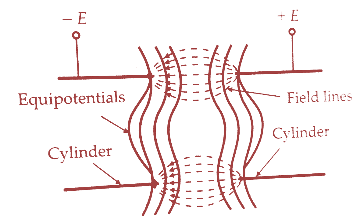
The figure below shows two concentric cylinders with a potential applied between them.Lateral repulsion again causes the spreading of the flux lines producing a field as shown.The equipotential surfaces are shown as solid lines.It is clear from the diagram that the equipotential surfaces are curved.
Electrostatic Focusing in Cathode Ray Oscilloscope(CRO):
Let us consider the region on the two sides of an equipotential surface S as shown in the below figure.The potential on the left side of the surface is -V and on the right side is +V.Let an electron moving in a direction AB enter the area to the left of S.This electron experiences a force which is normal to the surface S and is thus accelerated.
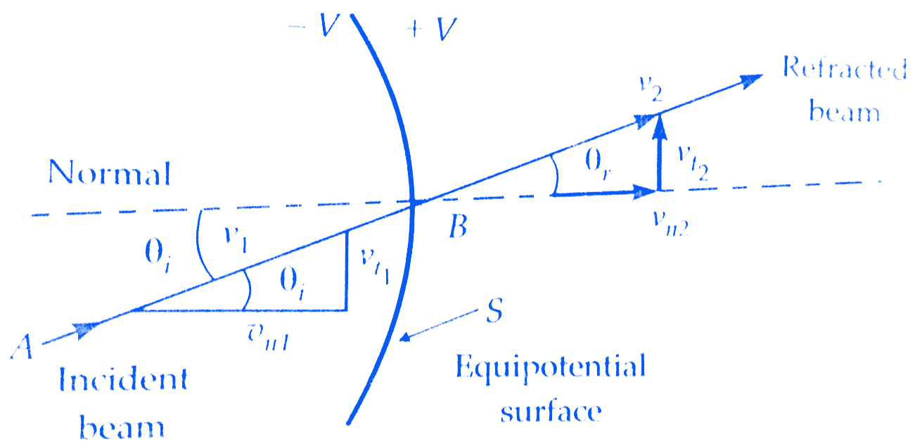
Since the force acts in a direction normal to the surface, it is the normal component of velocity that is increased after refraction while the tangential component remains the same.
The tangential components are :
Vt1 = V1 SIN θi and Vt2 = V2 SIN θ
Now Vt1 = Vt2 or V1 SIN θi = V1 SIN θr
∴ SIN θi/SIN θr = V2/V1
where
V1 = initial velocity of electrons
V2 = velocity of electrons after leaving surface S
θi = angle of incidence
θr = angle of refraction
The equation above is identical to the expression relating the refraction of a light beam in geometrical optics.
The refraction of an electron beam follows as the bending of a light beam at a retracting surface such as an optical lens.For this reason, the focusing system in a CRT is known as electron lens.The below figure shows the functional diagram of an electrostatic focusing in Cathode Ray Oscilloscope.The pre-accelerating anode, which is a metal cylinder containing many baffles, collimates the electron beam which enters it through a small opening on the left hand side.The pre-accelerating anode is connected to a high positive potential.
Must Read:
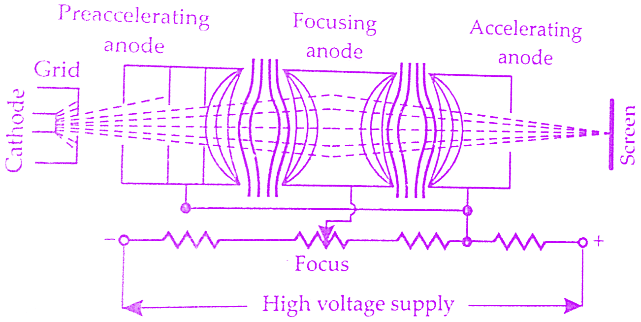
The focusing anode and the accelerating anodes are co-axial with the pre-accelerating anode.The pre-accelerating and accelerating anodes are connected to the same potential while the focusing anode is connected to a lower potential.On account of the difference of potential between focusing anode and the two accelerating anodes, a non-uniform field exists on each of the two ends of the focusing anode.The equipotential surfaces, thus, form a “double concave lens”.
The electron beams entering the field at angles other than the normal to the equipotential surfaces will be deflected towards the normal and the beam is thus focused towards the centre of the tube axis.By changing the voltage of the focusing anode, the refractive index of the electron lens is changed and therefore the focal point of the beam can be changed.The change in voltage is brought about by changing the setting of a potentiometer.This control is brought to the front panel of CRO and is marked FOCUS.
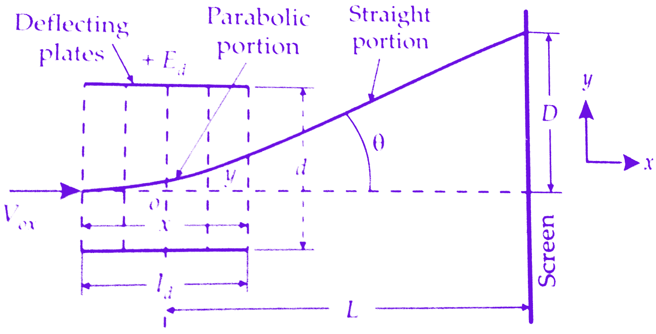
Electrostatic deflection derivation of cathode ray oscilloscope(CRO):
The figure below shows a general arrangement for electrostatic deflection in cro.There are two parallel plates with a potential applied between.These plates produced a uniform an electrostatic field in the Y direction.Thus any electron entering the field will experience a force in the Y direction and will be acceleratedin that direction.There is no force either in X direction or Z direction and hence there will be no acceleration of electrons in these directions.Now we will derive the equation of electrostatic deflection in crt tube.
 |
| Electrostatic deflection |
Let
E0 = voltage of pre-accelerating anode ; V
e = charge of an electron; C
m = mass of electron ; kg
Vox = velocity of electron when entering the field of deflecting plates; m/s
Ed = potential between deflecting plates; V
d = distance between deflecting plates; m
ld = Length of deflecting plates; m
L = distance between screen and the centre of the deflecting plates; m
D = deflecting of electron beam on the screen in Y direction
The loss of potential energy(P.E) when the electron moves from cathode to accelerating anode;
P.E = e Ea
The gain in kinetic energy(K.E.) by an electron
K.E = (½)mV²ox
Equating the two energies, we get
Vox = (2eEa/m)¹⁄²
This is the velocity of the electron in the X direction when it enters the deflecting that plates.The velocity in the X direction remains the same throughout the passage of electrons through the deflecting plates as there is no force acting in this direction.
The electric field intensity in the Y direction;
εy = Ed/d
Force acting on an electron in Y direction;
Fy = eεy = eEd/d
Suppose ay is the acceleration of the electron in Y direction, therefore,
Fy = may
ay = eεy/m
As there is no initial velocity in the Y direction the displacement y at any instant t in the Y direction is;
y = (½)ayt² = (½)(eεy/m)t²
As the velocity in X direction is constant, the displacement in X direction is given by,
x = Vox.t
∴ t = x/Vox
Submitting the above value t ;
y = (½)(eεy/m)(x/Vox)²
This is the equation of a parabola. The slope at any point (x,y) is
dy/dx = eεy/mV²ox
Put x = ld in above equation we get the value of .
Tan θ = (eεy/mV²ox).ld = (e.Ed.ld)/mdV²ox
After leaving the Electrostatic deflection plates, electrons travel in a straight line. The straight line of travel of electrons is tangent to the parabola at x=ld and this tangent intersects the X-axis at point O.The location of this point is given by,
x = y/tan θ = (eεy/2mV²ox).l²d/(eεy/mV²ox).ld = ld/2
The Apparent origin is thus at the centre of deflection plates.The deflection D on the screen is given by,
D = L tan θ = L.(e.Ed.ld)/mdV²ox
Substituting the value of V²ox = 2eEa/m in above equation,we get
D = L.(e.Ed.ld)/md × m/2eEa = L.Ed.ld/2dEa
Must Read:
From the above equation, we conclude,
(i) For a given accelerating voltage Ea and for particular dimensions of CRT, the deflection of the electron beam is directly proportional to the deflecting voltage. This means that the CRT may be used as a linear indicating device.
(ii) The discussion above assumes that Ed is a fixed dc voltage.The deflection voltage is usually a time varying quantity and the image of the screen thus follows the variations of the deflection voltage in a linear manner.
(iii)The deflection is independent of the e/m ratio.In a cathode ray tube, in addition to the electrons many types of negative ions such as oxygen, chlorine, carbon etc., are present.With electrostatic deflection system, because deflection is independent of e/m ratio, the ions travel with the electrons and are not concentrated at one point.Hence cathode ray tube with electrostatic deflection system does not produce an ion burn.
Conclusion:
Now here we have discussed electrostatic focusing in cathode ray oscilloscope and electrostatic deflection derivation in cathode ray oscilloscope(CRO).You can download this notes to your device in pdf, ppt format.
Comment below for any Queries.
Learn how to derive deflection sensitivity of cathode ray tube
Thank you for your interest in learning how to derive the deflection sensitivity of a cathode ray tube! This can be a complex topic, but with some guidance and practice, it can be understood. I hope that the resources available to you are helpful in achieving a thorough understanding of this subject. Best of luck in your learning journey!
Very Useful Derivation.
Thank you, Indu, for your comment about the derivation. I’m glad that you found it useful!