Electrodynamometer Type Wattmeter:
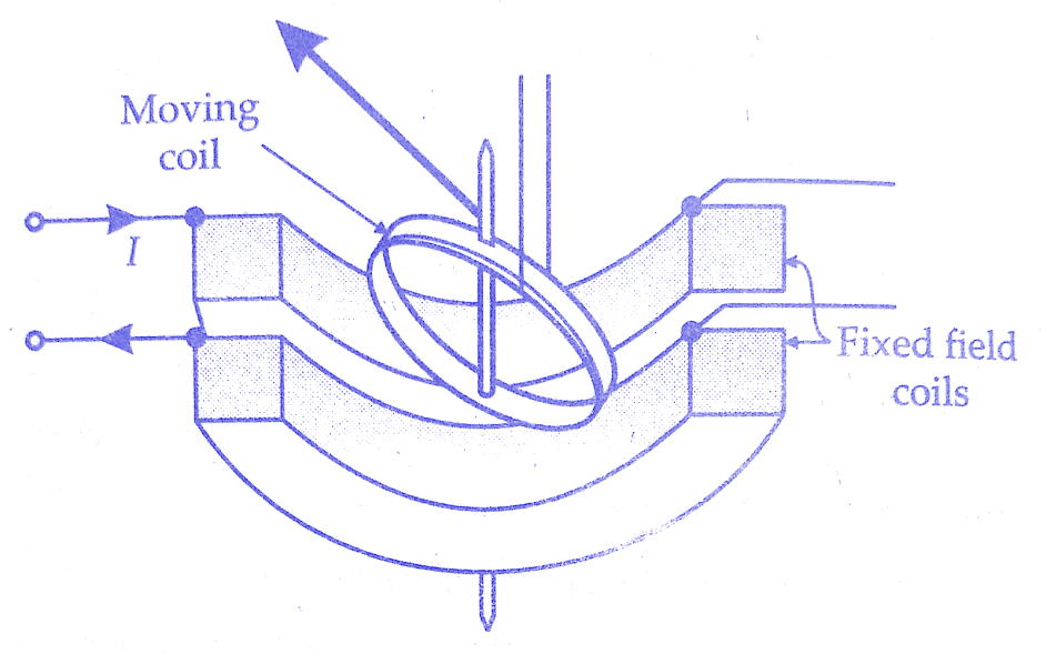
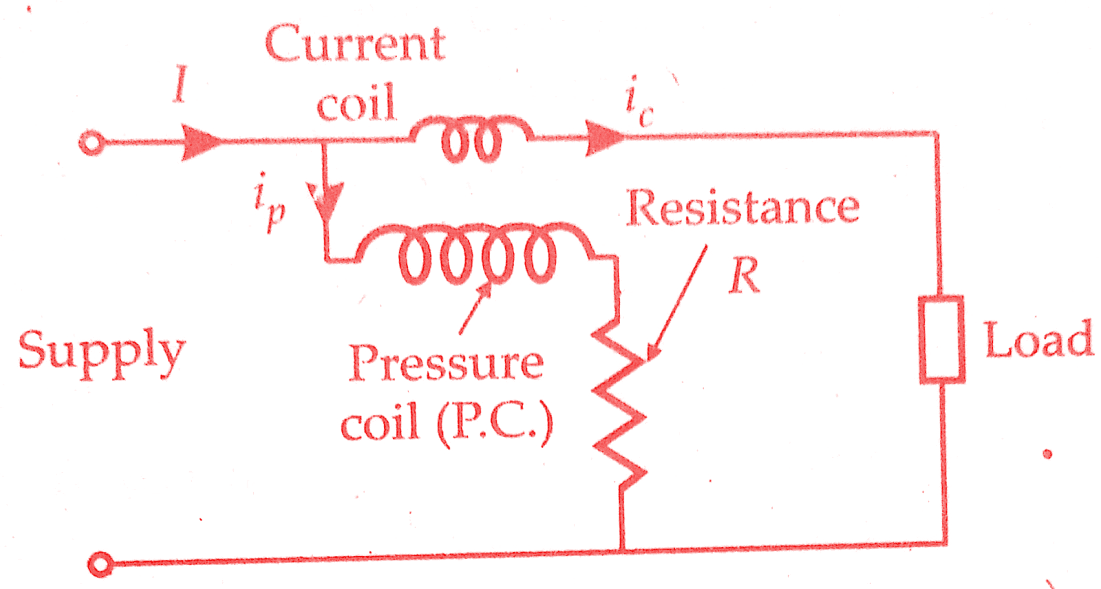
We will discuss Electrodynamometer Type Wattmeter working principle and its construction. These instruments are similar in design and construction to electrodynamometer type ammeters and voltmeters. The two coils are connected in different circuits for measurement of power. The fixed coils or “field coils” are connected in series with the load and so carry the current in the circuit. The fixed coils, therefore, form the “current coil” or simply CC of the wattmeter.
The moving coil is connected across the voltage and, therefore, carries a current proportional to the voltage. A high non-inductive resistance is connected in series with the moving coil to limit the current to a small value. Since the moving coil carries a current proportional to the voltage, it is called the “pressure coil” or “voltage coil” or simply called PC of the wattmeter.
Must Read:
- Damping torque or systems in indicating measuring instruments
- Controlling torque or system in indicating measuring instrument
Construction of Electrodynamometer Type Wattmeter:
1)Fixed coils:
The fixed coils carry the current of the circuit. They are divided into two halves. The reason for using fixed coils as current coils is that they can be made more massive and can be easily constructed to carry considerable current since they present no problem of leading the current in or out.
The fixed coils are wound with heavy wire. This wire is stranded or laminated especially when carrying heavy currents in order to avoid eddy current losses in conductors. The fixed coils of earlier wattmeters were designed to carry a current of 100 A but modern designs usually limit the maximum current ranges of wattmeters to about 20 A. For power measurements involving large load currents, it is usually better to use a 5 A wattmeter in conjunction with a current transformer of suitable range.
In the case of precision wattmeters, the two halves of the fixed coil, which are connected in series for a basic measuring range, can be connected in parallel to increase the Electrodynamometer wattmeter current range to twice its original value. Shunts are not used for extension of current range since they are subject to temperature errors.
2)Moving coil:
The moving coil is mounted on a pivoted spindle and is entirely embraced by the fixed current coils. Spring control is used for the movement. The figure below shows an electrodynamometer wattmeter. The use of moving coil as pressure coil is a natural consequence of design requirements.
 |
| Electrodynamometer wattmeter |
Since the current of the moving coil is carried by the instrument springs, it is limited to values which can be carried safely by springs without appreciable heating.A series resistor is used in the voltage circuit, and the current limited to a small value, usually up to 100 mA.
Both fixed and moving coils are air cored. The voltage rating of the wattmeter is limited to about 600 V by the power requirements of the voltage circuit since most of the power is absorbed by the resistance in series with the moving coil and considerable heat is generated. For higher voltages, the pressure coil circuit is designed for 110 V, and a potential transformer is used to step down the voltage.
3)Control:
Spring control is used for the instrument.
4)Damping:
Air friction damping is used. The moving system carries a light aluminium vane which moves in a sector shaped box. Electromagnetic or eddy current damping is not used as the introduction of a permanent magnet (for damping purposes) will greatly distort the weak operating magnetic field.
5)Scales and pointers:
They are equipped with mirror type scales and knife edge pointers to remove reading errors due to parallax.
Electrodynamometer Wattmeter Working Principle:
The instantaneous torque of an electrodynamometer instruments is given by
Ti = i1 i2 dM/dθ
where i1 and i2 are instantaneous values of currents in two coils.
Let V and I be the r.m.s. values of voltage and current being measured.
∴ The instantaneous value of the voltage across the pressure coil circuit
v = √2 V sinωt
If the pressure coil circuit has a very high. resistance, it can be mated as purely resistive.Therefore, current ip in the pressure coil is in phase with the voltage and its instantaneous value is
ip = v/ip = √2 V / (Rp) sinωt = √2 ip sinωt
here ip = Vp/Rp
= rms value of current M pressure coil circuit
Rp = resistance of pressure coil circuit.
If the current in the current coil lags the voltage in phase by an angle 4 instantaneous value of current through current coil is
ip = √2 I sin(ωt-∅)
∴ Instantaneous torque,
Ti = √2 I sinωt × √2 I sin(ωt-∅) dM/dθ
= 2 ip I sinωt sin(ωt-∅) dM/dθ
= ip I (cos ∅ – cos(2ωt-∅)) dM/dθ
It is clear from above that there is a component of power which varies as twice the frequency of current and voltage (mark the term containing 2ωr).
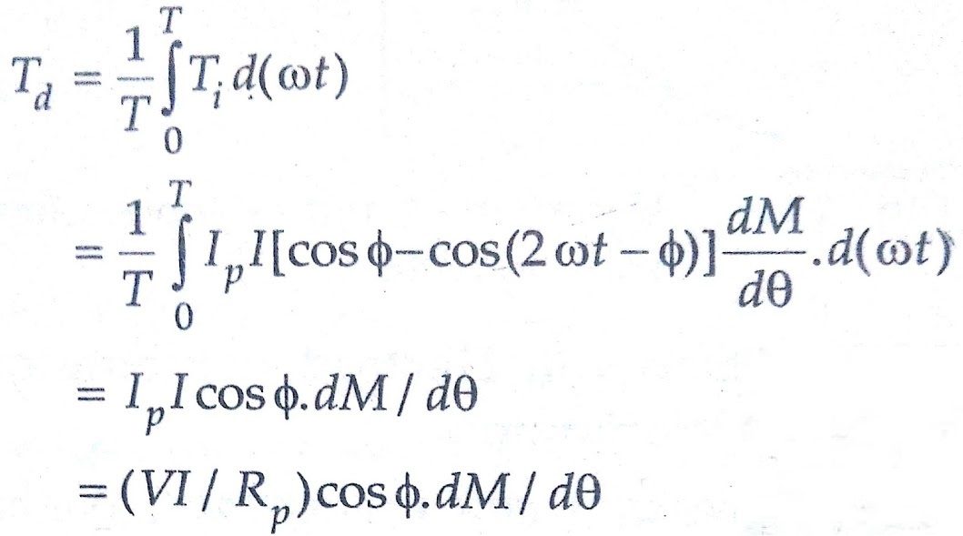
Average deflecting torque,
Controlling torque exerted by springs,
Tc = Kθ
where K = spring constant
and θ = final steady deflection.
Since the moving system of the Electrodynamometer Type Wattmeter cannot follow the rapid variations in torque (the torque has a double frequency, component), it will take up a position at which the average deflection torque is equal to the restoring torque of the springs.
At balance position,
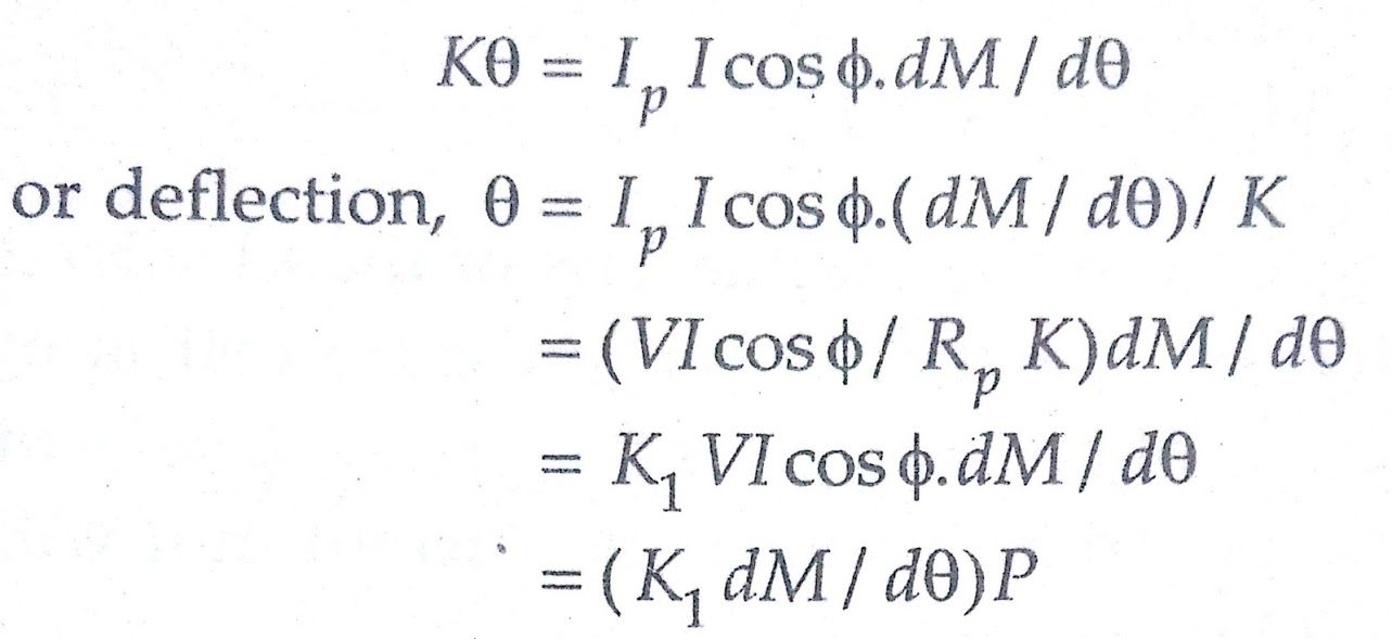
where P = power being measured =VI cos θ
and K1 = 1/RpK
Conclusion:
Today we have learnt about Electrodynamometer Type Wattmeter Working Principle & Construction.You can download this article as pdf, ppt.
Comment below for any Queries.