Controlling Torque in Indicating Instrument:
We already know that an electrical indicating instrument will use a dial and pointer to display the magnitude.Due to this controlling torque in indicating instrument, the current produces deflection of the pointer proportional to its magnitude.The system producing a controlling torque is called a “Controlling System“.
The functions of the controlling system are :
(i) To produce a force equal and opposite to the deflecting torque at the final steady position of the pointer in order to make the deflection of the pointer definite for a particular magnitude of current.In the absence of a controlling system, the pointer will shoot (swing) beyond the final steady position for any magnitude of current and thus the deflection will be indefinite.
(ii) To bring the moving system back to zero when the force causing the instrument deflecting system to deflect is removed. In the absence of a controlling system, the pointer will not come back to zero when current is removed.Controlling torque is usually provided by springs.
Must Read:
Controlling System in Indicating Measuring Instruments:
The deflecting system of most of the commercial instruments is mounted on a pivoted spindle, the quantity being measured producing a deflecting torque proportional to its magnitude. There are two types of controlling torques which are used for such a mounted system
(i) Gravity control
(ii) Spring control
1.Gravity control:
In gravity control, a small weight is placed on an arm attached to the deflecting system.The position of this weight is adjustable.This weight produces a controlling torque due to gravity.The figure right side shows the pointer at zero position.In this case, the control torque is zero.Suppose the system deflects through an angle θ as shown in the figure below.The weight acts at a distance ‘l’ from the centre, the component of weight trying to restore the pointer back to zero position is W sin θ.Therefore, controlling torque is :
Tc = W Sin θ × l = Wl Sin θ
= Kg . Sin θ
where Kg = Wl = a constant
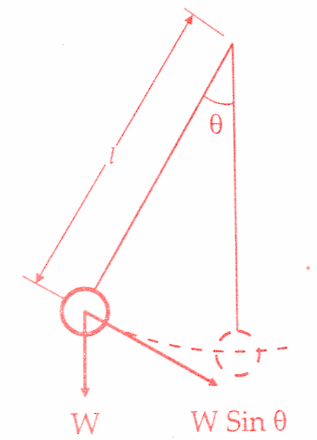 |
| Gravity Control |
Thus the controlling torque is proportional to the sine of the angle of deflection of moving system. The controlling torque can be varied by simply adjusting the position of control weight upon the arm which carries it.
This textbook “Electrical and Electronics Measurements by S. Chand” is the best in industry. Grab it now for very less price.
It is obvious that the instruments employing gravity control must be used in a vertical position in order that the control may operate. The instruments must be mounted in level position otherwise, there will be a very serious zero error. For these reasons, gravity control is not suited for indicating instruments in general and portable instruments in particular.The system is normally not used now except in cases where cost and simplicity is the primary consideration.
2. Spring control:
A hair spring attached to the moving system (the below figure) exerts a controlling torque.The essential requirements for instrument springs are :
(i) They should be non-magnetic
(ii) They should be proof from mechanical fatigue
(iii) Where springs are used to lead current into the moving system.They should have a small sufficient to carry the current without temperature rise affecting their constant.They should also have a low resistance temperature coefficient.
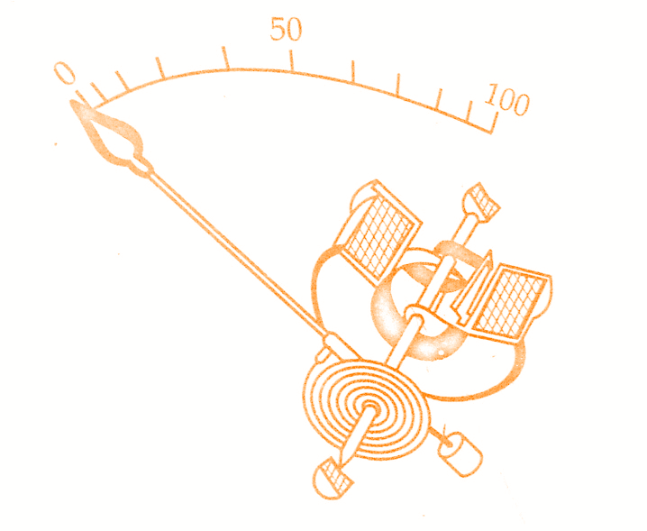 |
| Spring Control |
A number of non-magnetic materials like silicon bronze, hard rolled silver or copper, platinum silver, platinum-iridium and German silver have been used but have not been found satisfactory owing to some reason or the other. For most applications phosphor bronze has been found to be the most suitable material except in instruments of low resistance (like millivoltmeters).In this case, some special bronze alloys having low resistance may be used with some sacrifice in mechanical quality.
Must Read:
Flat spiral springs as shown below are used in almost all indicating instruments as the space required by these springs is less than for other types.
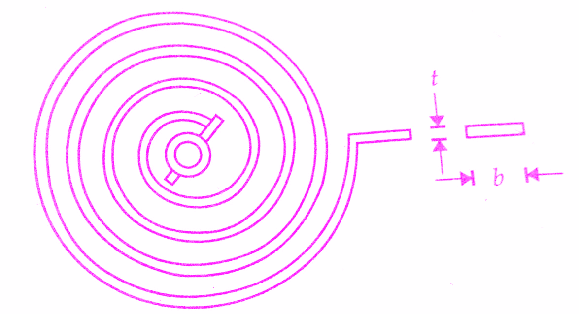 |
| Flat Spiral Spring |
One form of control spring mounting is shown in the above figure.The inner end of the spring is attached to the spindle and the outer end carries a spigot which engages in a circular disc surrounding the jewel screw. This disc carries an arm which is slotted and splayed out at the end. The purpose of slotted extension arm is to allow the spring to be coiled or uncoiled slightly, so that the pointer may be set at zero. The slotted arm is actuated by a set screw mounted at the front of the instrument and, therefore, zero setting of the instrument can be done without removing the cover.
By making the number of turns large, the deformation per unit length is kept small on full scale deflection.The controlling torque is thus made proportional to the angle of deflection of the deflecting system.
For a flat spiral spring, the controlling torque developed by deflection is :
Tc = Ebt³θ /12.l N-m
where E = Young’s modulus of spring material ; N /m³,
b = width of spring ; m,
t = thickness of spring ; m,
1= length of spring ; m
θ = angular deflection ; rad.
E, b, t, 1 are constant for a particular spring.
∴ Tc = K θ
where K = Ebt³ /12.l Nm/rad
= a constant called ‘spring constant’ or ‘control constant’ or ‘torsion constant’ or ‘restoring constant’.
The springs should be stressed well below their elastic limit at maximum deflection of the instrument in order that there is no permanent set or that no change in deflection (or zero shift) will occur from the inelastic field.
Max. fibre stress fmax = 6Tc /bt² N/m²
By writing Tc value we get
l/t = (E/fmax).(θ/2)
For phosphor bronze, the maximum allowable stress is fmax = 30 MN/m², and E =120 GN/m²
From this, l/t = (120×10⁹)/(30×10⁹) . θ/2
Therefore, for a full scale deflection of θ = π/2 and hence l/t= 3000.
Hence in order that the material is not over-stressed the ratio of length to thickness of the spring strip should not be much less than 3000. Some designers use a ratio as low as 2100 (for a maximum deflection of 90°) for portable instruments.For switchboard instruments, whose indications are of lower precision, a ratio as low as 1000 is sometimes used.The ratio b/t may be as high as 30/1 but is generally greater than 10/1.
This textbook “Electrical and Electronics Measurements by S. Chand” is the best in industry. Grab it now for very less price.
Fatigue in springs may be avoided to a great extent by proper annealing and ageing during manufacture. In order to eliminate the effect of temperature variations upon the length of the spring, two springs coiled in opposite directions are used. When the moving system deflects, one spring is extended while the other is compressed.
Comparison between Spring and Gravity Control :
The disadvantages of gravity control have been described earlier.They are
(i) This type of control can be used in only vertically mounted instruments and
(ii) In case gravity control is used, the instruments must be perfectly levelled.
Its advantages, when compared with spring control, are
(i) It is cheap.
(ii) The control is independent of temperature
(iii)It does not deteriorate with time
Conclusion:
Now here we have discussed the controlling torque and controlling system used in indicating measuring instrument.You can download this article as pdf,ppt.
Comment below for any Queries.