Synchronization of Three Phase Alternators:
The conditions to be satisfied for synchronization of three phase alternators are same as that for single phase alternators. As discussed earlier the following are conditions for synchronization of alternators:
i) The terminal voltage of the incoming machine must be same as that of bus bar voltage.
ii) The frequency must be same as that of the incoming machine as well as that of the bus bar. This necessitates that speed must be properly adjusted
(f = PN/120).
iii) Phase sequence for the two voltages must be same with respect to the external load.
Must Read:
- Synchronization of Single Phase Alternators
- Principle and working of Synchronous generator or alternator
But instead of saying that voltages must act in phase opposition, the phase sequence must be same i.e phases must be connected in proper order of R, N, B.Typical setup for synchronization of three Phase alternators is shown in the below figure.
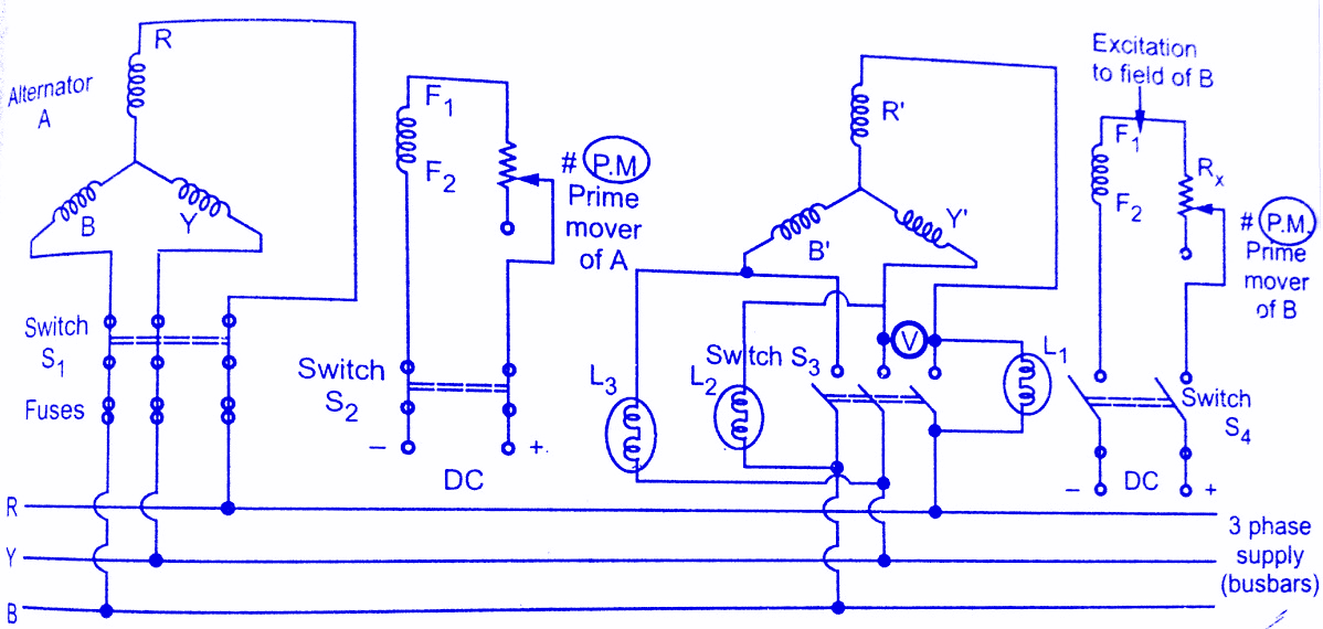 |
| Setup for synchronization of three Phase alternators |
In synchronizing three phase alternators, three lamps are connected as shown in the below figure, so that it can be used to indicate whether the incoming machine is running slow or fast.With the symmetrical connection of lamps, they would dark out or glow up simultaneously provided that phase sequence is same for incoming machine and bus bar.
Consider the two alternators A and B to be synchronized.The alternator A is already running at synchronous speed and its excitation is so adjusted that it builds up the rated voltage.The alternator A is connected to the bus bars of constant voltage and frequency.The alternator B is to be connected to bus bar i.e. it is to be synchronized with alternator A.The process of synchronization of three Phase Alternators can be explained as below:
Step 1: Start the prime mover of the machine.Adjust its speed to a synchronous speed of machine B.This will rotate the rotor of alternator B at synchronous speed.
Step 2: The switch S4 is then closed.By adjusting the rheostat Rx the excitation to the field is adjusted so that induced emf of B is equal to the induced e.m.f. of A. This can be verified by a voltmeter.
Step 3: To satisfy remaining conditions, the three lamp pairs are used which are L1, L2, and L3 as shown in the above figure.These are connected in such a way that pair L1 is straight connected while the pairs L2 and L3 are cross connected.
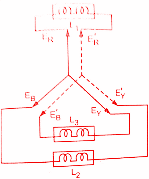
To understand the connection, the pairs are again shown in the above figure.Now two supplies are supplying lamp pairs, ERYB i.e voltage supply of bus bar while ER’Y’B’. i.e supply generated by alternator B.The switch S3 is still open.
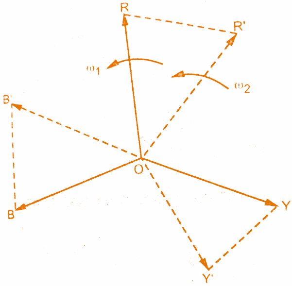
Let the three busbar voltages be represented by phasors OR, OY, OB rotating at angular of ω1 rad/s.The incoming alternator voltages are represented by phasors OR’, OY’, OB’ rotate angular speed of ω2 rad/s.The phasor ERR’, joining the tips R and R’ is the voltage across lamp pair L1.Similarly, EYB’ and EBY’ are voltages across lamps L2 and L3 respectively.
If there is a difference between the two frequencies due to the difference in speeds of the two alternators, the lamps will become dark and bright in a sequence.This sequence tells whether incoming alternator frequency is less or greater than machine A.
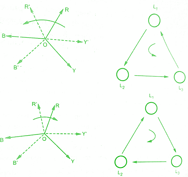
The sequence L1, L2, L3 tells that machine B is faster as the voltage star R’Y’B’ will appear to rotate anticlockwise with respect to bus bar voltage RYB at a speed corresponding to the difference between their frequencies shown in the below figure.
The sequence L3, L2, L1 tells that the machine B is slower because voltage star R’ Y’ B’ will appear to rotate clockwise with respect to bus bar voltage RYB.The prime mover speed can be adjusted accordingly to match the frequencies.
The synchronization of three Phase alternators is done at the moment when Lamp L1 is in the middle of the dark period.If the lamps pair becoming dark and bright simultaneously, it indicates incorrect phase sequence which can be corrected by interchanging any two leads either of the incoming machine or of bus bars.
Key Point: For high voltage alternators, it is not possible to use the lamps directly.In such cases, lamps are through potential transformers.
In this method of synchronization of three phase alternators when lamp L1 is dark the other two lamp pairs L2 and L3 and equally bright.So this method of synchronization is called “Lamps bright and dark methods“.
Synchronization by Synchroscope:
It can be seen that the method described in earlier section i.e. Lamps dark & bright method is not accurate since it requires a correct sense of judgement of the operator.Hence to avoid the personal judgement, the machines are synchronized by an accurate device known as synchroscope.
It consists of a rotating pointer which indicates the exact moment of closing the synchronizing switch.If the pointer rotates in an anticlockwise direction, it indicates that incoming machine is running slow whereas clockwise rotation of pointer indicates that incoming machine is running faster.The rotation of pointer is proportional to the difference in the two frequencies.The pointer should rotate at a very low speed in the direction of the arrow marked fast as shown in the below figure.
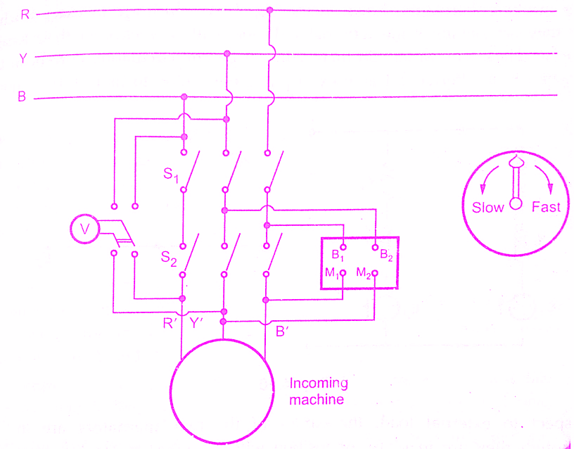 |
| Synchronization by Synchroscope |
When the rotating pointer reaches the vertical position at slow speed the switch must be closed.The pointer will oscillate about some mean position instead of rotating if the difference in frequencies is large.In such cases, the speed of the incoming machine is adjusted properly.
The connections for Synchronization by Synchroscope are shown in the above figure.Any two bus bar connected to its terminals while its other terminals are connected to corresponding lines of the incoming machine.The phase sequence from bus bar and from the machine must be same.It can be checked with the help of phase sequence indicator.The voltmeter is used to check the equality of voltages of the bus bar and incoming machine.The Synchronization by Synchroscope procedure is already explained before.
Key Point: The best methods used are synchrozisation of synchroscope and use of lamps together.
Also Read:
Now-a-days automatic synchronizing devices are also available which will perform the entire process of synchronization by Synchroscope automatically without the help of shift engineer.But schemes are more complicated and may take larger time than required by a shift engineer.
Conclusion:
Here we have learnt about Synchronization of three Phase Alternators and Synchronization by Synchroscope.You can download this article as pdf, ppt.
Comment below for any Queries.