Auto Transformer:
Now we let us discuss autotransformer which is a special case of Transformers and why do we use auto transformer.The primary and secondary windings of a two winding transformer have induced emf in them due to a common mutual flux and hence are in phase.The currents drawn by these two windings are out of phase by 180◦.This prompted the use of a part of the primary as secondary.This is equivalent to fusing the secondary turns into primary turns.The fused section needs to have a cross sectional area of the conductor to carry (I2 –I1) ampere.
 |
| Auto transformer |
Auto Transformer Construction:
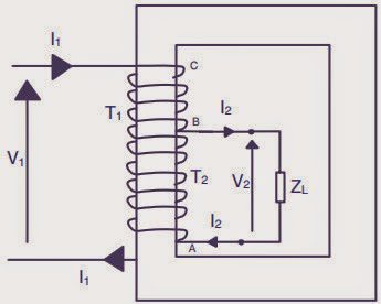
This ingenious thought led to the invention of an autotransformer.The figure shows the physical arrangement of an auto transformer.The total number of turns between A and C are T1.At point B a connection is taken. Section AB has T2 turns. As the volts per turn, which is proportional to the flux in the machine, is the same for the whole winding,
V1 : V2 = T1 : T2
For simplifying the analysis, the magnetizing current of the transformer is neglected.When the secondary winding delivers a load current of I2 ampere the demagnetizing ampere turns is I2T2.This will be countered by a current I1 flowing from the source through the T1 turns such that,
I1T1 = I2T2
Auto Transformer Working:
A current of I1 ampere flows through the winding between B and C. The current in the winding between A and B is (I2 – I1) ampere.The cross section of the wire to be selected for AB is proportional to this current assuming a constant current density for the whole winding.Thus some amount of material saving can be achieved compared to a two winding transformer.The magnetic circuit is assumed to be identical and hence there is no saving in the same.To quantify the saving the total quantity of copper used in an auto transformer is expressed as a fraction of that used in a two winding transformeras,
This means that an auto transformer requires the use of a lesser quantity of copper given by the ratio of turns.This ratio, therefore, denotes the savings in copper.As the space for the second winding need not be there, the window space can be less for an auto transformer, giving some saving in the lamination weight also.The larger the ratio of the voltages, smaller is the savings.As T2 approaches T1 the savings become significant.Thus auto transformers become an ideal choice for close ratio transformations.The savings in material is obtained, however, at a price.The electrical isolation between primary and secondary has to be sacrificed.
If we are not looking at the savings in the material, even then going in for the autotransformer type of connection can be used with advantage, to obtain a higher output.This can be illustrated as follows.Fig. 29 shows a regular two winding transformer of a voltage ratio V1 : V2, the volt ampere rating being V1I1 = V2I2 = S.If now the primary is connected across a supply of V1 volt and the secondary is connected in series addition manner with the primary winding, the output voltage becomes (V1+V2) volt.The new output of this autotransformer will now be
Thus an increased rating can be obtained compared to a two winding transformer with the same material content.The windings can be connected in series opposition fashion also.Then the new output rating will be
The differential connection is not used as it is not advantageous as the cumulative connection.This is about autotransformer construction and working.