Losses in Transformers:
We all know that all machines have losses.Similarly, a Transformer also has some losses called transformer losses.Its losses are almost similar to that of d.c. machines except transformers do not have mechanical losses because all of its parts are stationary(no moving parts).
So all losses in transformer are explained in detail below:
1. Primary copper loss
2. Secondary copper loss
3. Iron loss
4. Dielectric loss
5. Stray load loss
1.Primary copper losses:
These copper losses in transformer occur due to the flow of current through the primary windings of a transformer which possess some resistance.
2.Secondary copper losses:
These copper losses in transformer occur due to the flow of current through the secondary windings of a transformer which also has resistance.
![]()
The primary and secondary resistances differ from their d.c. values due to skin effect and the temperature rise of the windings.While the average temperature rise can be approximately used, the skin effect is harder to get analytically. The short circuit test gives the value of Re taking into account the skin effect.
3.Iron losses or Core losses:
These losses include Eddy current losses and Hysteresis losses in Transformers.They both depend upon the magnetic properties of the material used for the construction of core.
(i)Eddy current losses:
When AC supply is given to primary windings of a transformer, an alternating flux is developed.This alternating magnetic flux links with secondary windings of transformer and an emf is induced in it.As we are aware that, the core of transformer is made of steel or iron, that alternating flux also cuts this iron parts or core of transformer, and emf is also induced in those parts which causes some circulating currents to flow through it.These circulating currents are also called eddy currents.Due to this eddy currents some amount of energy is lost in the form of heat.The power loss due to eddy currents is given by
![]()
As the lamination thickness is much smaller than the depth of penetration of the field, the eddy current loss can be reduced by reducing the thickness of the lamination.Present day laminations are of 0.25 mm thickness and are capable of operation at 2 Tesla.These reduce the eddy current losses in the core.This loss also remains constant due to constant voltage and frequency of operation.
(ii)Hysteresis losses:
Hysteresis loss is a heat loss caused by the magnetic properties of the core.If the magnetic field applied to a magnetic material is increased and then decreased back to its original value, the magnetic field inside the material does not return to its original value.The internal field lags behind the external field. This behaviour results in a loss of energy, called the hysteresis loss when a sample is repeatedly magnetized and demagnetized.It can simply stated that losses occurring due to the reversal of magnetization of a transformer.Hysteresis loss can be given by Steinmetz formula:
This loss depends upon the volume of the transformer core, frequency and flux density.The sum of hysteresis and eddy current losses can be obtained by the open circuit test.
4. Dielectric loss:
The dielectric losses take place in the insulation of the transformer due to the large electric stress.In the case of low voltage transformers, this can be neglected.For constant voltage operation, this can be assumed to be a constant.
5.Stray load loss:
The stray load losses arise out of the leakage fluxes of the transformer.These leakage fluxes link the metallic structural parts, tank etc. and produce eddy current losses in them.Thus they take place ’all round’ the transformer instead of a definite place, hence the name ’stray’.Also, the leakage flux is directly proportional to the load current, unlike the mutual flux which is proportional to the applied voltage.
Hence this loss is called ‘stray load loss‘.This can also be estimated experimentally.It can be modeled by another resistance in the series branch in the equivalent circuit.The stray load losses are very low in air-cored transformers due to the absence of the metallic tank.
Thus, the different losses fall into two categories Constant losses (mainly voltage dependant) and Variable losses (current dependant).The expression for the efficiency of the transformer operating at a fractional load x of its rating, at a load power factor of θ2, can be written as
![]()
Here S in the volt ampere rating of the transformer (V′2I′2 at full load), Pconst being constant losses and Pvar the variable losses at full load.
For a given power factor an expression for η in terms of the variable x is thus obtained.By differentiating η with respect to x and equating the same to zero, the condition for maximum efficiency is obtained.In the present case, that condition comes out to be
![]()
That is, when constant losses equal the variable losses at any fractional load x the efficiency reaches a maximum value.The maximum value of that efficiency at any given power factor is given by,
![]()
From the expression for the maximum efficiency it can be easily deduced that this maximum value increases with increase in power factor and is zero at zero power factor of the load.It may be considered a good practice to select the operating load point to be at the maximum efficiency point.Thus if a transformer is on full load, for the most part of the time then the ηmax can be made to occur at full load by proper selection of constant and variable losses. However, in the modern transformers, the iron losses are so low that it is practically impossible to reduce the full load copper losses to that value.Such a design wastes lot of copper.
Efficiency of Transformer:
As is the case with other types of electrical machines, the efficiency of transformer at a particular load and power factor is defined as the output divided by the input the two being measured in the same units (either watts or kilowatts).
![]()
But a transformer being a highly efficient piece of equipment has a very small loss, hence it is impractical to try to measure transformer, efficiency by measuring input and output.These quantities are nearly of the same size.A better method is to determine the losses and then to calculate the efficiency from;
![]()
![]()
It may be noted here that efficiency is based on power output in watts and not in volt-amperes, although losses are proportional to VA.Hence, at any volt-ampere load, the efficiency depends on power factor, being maximum at a power factor of unity.Efficiency can be computed by determining core loss from no-load or open-circuit test and Cu loss from the short-circuit test.
All day efficiency:
Large capacity transformers used in power systems are classified broadly into Power transformers and Distribution transformers.The former variety is seen in generating stations and large substations.Distribution transformers are seen at the distribution substations.The basic difference between the two types arise from the fact that the power transformers are switched in or out of the circuit depending upon the load to be handled by them.
Thus at 50% load on the station, only 50% of the transformers need to be connected in the circuit.On the other hand, a distribution transformer is never switched off.It has to remain in the circuit irrespective of the load connected.In such cases, the constant loss of the transformer continues to be dissipated.Hence the concept of energy based efficiency is defined for such transformers. It is called ’all day’ efficiency.
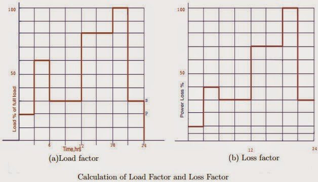
The all day efficiency is thus the ratio of the energy output of the transformer over a day to the corresponding energy input.One day is taken as a duration of time over which the load pattern repeats itself.This assumption, however, is far from being true.The power output varies from zero to full load depending on the requirement of the user and the load losses vary as the square of the fractional loads.The no-load losses or constant losses occur throughout the 24 hours.
Thus, the comparison of loads on different days becomes difficult. Even the load factor, which is given by the ratio of the average load to rated load, does not give satisfactory results.The calculation of the all day efficiency is illustrated below with an example.The graph of load on the transformer expressed as a fraction of the full load is plotted against time in Figure below.In an actual situation, the load on the transformer continuously changes.This has been presented by a stepped curve for convenience.The average load can be calculated by
![]()
where Pi is the load during an interval i.n intervals are assumed.xi is the fractional load.Si = xiSn where Sn is a nominal load.The average loss during the day is given by
![]()
This is a non-linear function.For the same load factor, different average loss can be there depending upon the values of xi and ti.Hence a better option would be to keep the constant losses very low to keep all day efficiency high.Variable losses are related to load and are associated with revenue earned.The constant losses, on the other hand, has to be incurred to make the service available.The concept of all day efficiency may, therefore, be more useful for comparing two transformers subjected to the same load cycle.
The concept of minimizing the lost energy comes into effect right from the time of procurement of the transformer.The constant losses and variable losses are capitalized and added to the material cost of the transformer in order to select the most competitive one, which gives minimum cost taking initial cost and running cost put together.Obviously, the iron losses are capitalized more in the process to give an effect to the maximization of energy efficiency.If the load cycle is known at this stage, it can also be incorporated in computation of the best transformer.