Voltage regulation of synchronous generator using EMF method:
Generally, we use this Synchronous Impedance Method for high-speed Alternators or synchronous generator. This method is also known as EMF method. Before calculating the voltage regulation we need to calculate the following data.
1.Armature Resistance per phase [Ra]
2.Open Circuit characteristics which is a graph between open circuit voltage [Vo.c.] and field current.
3.Short circuit characteristics which is a graph between short circuit current [Is.c.] and field current.
Must Read:
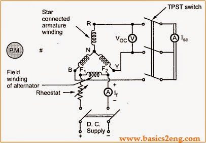
The circuit diagram to perform this O.C test and S.C test is given below.
The alternator or synchronous generator is coupled with the prime mover to drive alternator at synchronous speed.The armature of the alternator or synchronous generator is connected to TPST switch.The three terminals of the switch are short circuited by an ammeter.
The voltmeter is connected between two line terminals to measure o.c voltage of the alternator.For the purpose of excitation, a DC supply is connected field winding.A rheostat is also connected in series with DC supply which is used to vary the field current i.e field excitation.
 |
| Voltage Regulation Of Alternator Using Synchronous Impedance Method |
1. O.C test
Procedure:
1) By using the prime mover start the alternator or synchronous generator and adjust its speed to the Synchronous speed.
2)Note that rheostat should be in maximum position and switch on the D.C supply.
3)The T.P.S.T. switch should be kept open in the armature circuit.
4)Field current is varied from its min. value to the rated value using the rheostat.So now flux increases, which leads to increase in the induced e.m.f. The voltmeter now the actual line value of open circuit voltage.For various values of field currents, voltmeter readings are noted in a table.
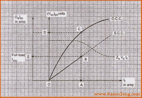
Now plot a graph between o.c phase voltage and field current.The graph obtained is called o.c.c .
2. S.C test
Procedure:
1)After the o.c test, the field rheostat should be kept at max. Position, reducing field current to min. value.
2)Now the T.P.S.T switch is closed.
3)The armature gets short circuited because ammeter has negligible resistance. Now increase the field excitation is increased gradually till full load current is obtained through armature windings.
This is observed on the ammeter connected in the armature circuit.Tabulate the values of field current and armature current values obtained.
4)Now plot a graph between s.c armature current and field current.The graph obtained is called S.C.C.
The S.C.C. is a straight line passing through origin but o.c.c resembles a B.H curve of a magnetic material.
 |
| Voltage Regulation Of Alternator Using Synchronous Impedance Method |
Voltage Regulation of synchronous generator Calculations:
Zs can be determined from O.C.C and S.C.C for any load condition.The value of Ra should be known now.So it can be measured by applying d.c known voltage across the two terminals.
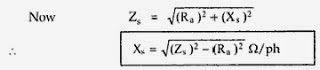
So now induced e.m.f per phase is calculated as follows:
![]()
Voltage regulation of alternator or synchronous generator is calculated by using the below formula,
![]()
The above is the Voltage regulation of alternator or synchronous generator formula using Synchronous Impedance Method or EMF Method.
Must Read: