What are Digital Voltmeters?
We already know about voltmeter. It is an electrical instrument used for measuring the potential difference present between two points. These voltmeters are of two types (i) Analog voltmeter (ii) Digital Voltmeter. This measured voltage can be either of AC or DC Analog voltmeters are made of a dial and a pointer to show the readings. But those instruments had many disadvantages like no accurate results, no precision etc, so those are replaced by digital voltmeters with a digital technology in it.
But these analog voltmeters are being used in some parts of the world. Now let us discuss how does a digital voltmeter work and working principle of digital voltmeters and block diagram.
 |
| Digital Voltmeters |
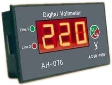
A digital voltmeter (DVM) displays the value of a.c. or d.c voltage being measured directly as discrete numerals in the decimal number. system. Numerical readout of DVMs is advantageous since it eliminates observational errors committed by operators. The errors on account of parallax and approximations are entirely eliminated. The use of digital voltmeters increases the speed with which readings can be taken. Also, the output of digital voltmeters can be fed to memory devices for storage and future computations.
A digital voltmeter is a versatile and accurate voltmeter which has many laboratory applications. On account of developments in the integrated circuit (IC) technology, it has been possible to reduce the size, power requirements and cost of digital voltmeters. In fact, for the same accuracy, a digital voltmeter now is less costly than its analog counterpart. The decrease in the size of DVMs on account of the use of ICs, the portability of the instruments has increased.
This textbook “Electrical and Electronics Measurements by S. Chand” is the best in industry. Grab it now for very less price.
Types of digital voltmeters :
The increasing popularity of DVMs has brought forth a wide number of types employing different circuits. The various types of Digital Voltmeters(DVM’s) in general use are :
(i) Ramp type digital voltmeter
(ii) Integrating type digital voltmeter
(iii) Potentiometric type digital voltmeter
(iv) Successive approximation type digital voltmeter
(v) Continuous balance type digital voltmeter
The circuits described here do not represent those of any specific make of a digital voltmeter. These circuits are being described merely to explain the voltage measuring principles on which these instruments operate.
Circuit or Block diagram of Digital Voltmeters:
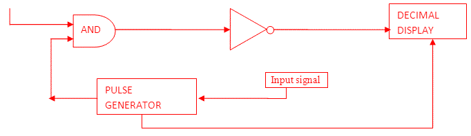
Block diagram of Digital Voltmeter
Working Principle of digital voltmeters:
From the above block diagram, the voltage to be measured is given to the input signal present in the circuit diagram. And next to this signal is processed onto the pulse generator which generates a train of rectangular pulses by using both analog and digital techniques.
The digital circuitry present inside the pulse generator will control the width and frequency while analog circuitry will control the amplitude, rise time and fall time of the pulse generator. When AND gate is fed with train pulse and rectangular pulse, it will give train pulses with the same duration of that of the rectangular pulse.
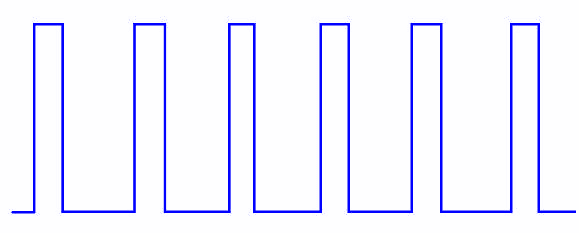
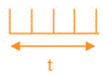
Train Pulse
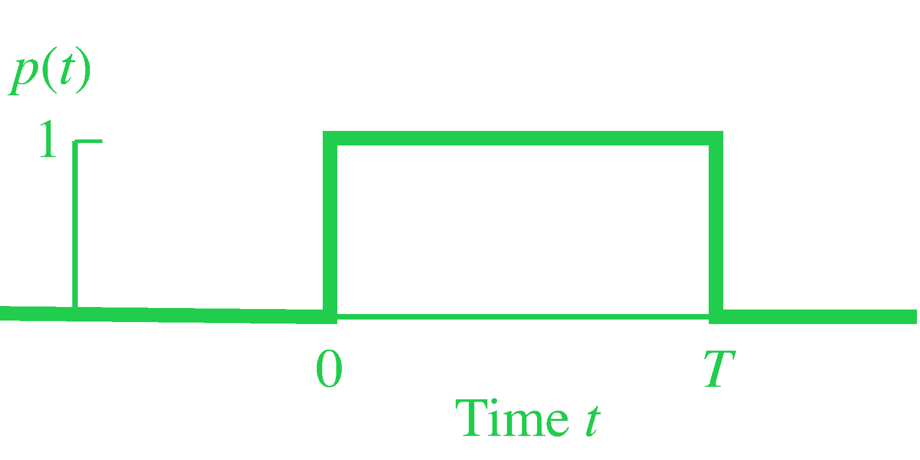
Rectangular pulse
OUTPUT of AND gate:
We can find the AND gate with not, so out will be inverted (NOT + AND)
OUTPUT of NOT gate:
![]()
Now the display screen will count duration and number of pulses and displays it on the screen. So here we used basic analog to digital conversion working principle in the digital voltmeter. Hence digital voltmeters can be made using the above analog to digital conversion principles.
In every case, the basic function that is performed is an analog to digital (A/D) conversion. For example, a voltage value may be changed to a proportional time interval, which starts and stops a clock oscillator. In turn, the oscillator output is applied to an electronic counter which is provided with a readout in terms of voltage values.
Advantages of Digital Voltmeters:
- Outputs on the screen are accurate without any errors
- Readings are taken faster
- Parallax error and approximation is entirely eliminated.
- Output can be stored in memory devices
- Versatile and accurate
- Power consumption is less
- Portable instrument
- Cheap cost and compact
Conclusion:
Now here we have discussed working principle and block diagram of digital voltmeters (DVM‘s) and their types also. You can download this page as pdf, ppt.
Comment below for any Queries.