Gas Turbine Power Plant:
Here I am going to explain you the different types of power generating stations or power plant. First, let us know what is the function of a power generating station. A power generating station or power plant uses various sources like hydel energy, thermal energy, diesel, nuclear energy to produce bulk electric power. Here now we are going to discuss how the energy of the gas turbine is used to generate power. So for that Gas Turbine power station or Gas turbine plant is employed.
A generating station which employs a gas turbine as the prime mover for the generation of electrical energy is known as a gas turbine power plant. In a gas turbine power plant, air is used as the working fluid. The air is compressed by the compressor and is led to the combustion chamber where heat is added to the air, thus raising its temperature. We will understand the gas turbine power plant layout and learn the diagram.
Heat is added to the compressed air either by burning fuel in the chamber or by the use of air heaters. The hot and high-pressure air from the combustion chamber is then passed to the gas turbine where it expands and does the mechanical work. The gas turbine drives the alternator which converts mechanical energy into electrical energy.
It may be mentioned here that compressor, gas turbine and the alternator are mounted on the same shaft so that a part of the mechanical power of the turbine can be utilised for the operation of the compressor. Gas turbine power plants are being used as standby plants for hydro-electric stations, as a starting plant for driving auxiliaries in power plants etc.

Must Read:
Gas Turbine Power Plant Schematic Diagram:
The gas turbine power plant layout is shown in the figure below. The main components of the Gas Turbine Power Plant are :
(i) Compressor
(ii) Regenerator
(iii) Combustion chamber
(iv) Gas turbine
(v) Alternator
(vi) Starting motor
This textbook “Principles of Power System by V.K Mehta” is the best in industry. Grab it now for very less price.
(i) Compressor: The compressor used in the plant is generally of rotatory type. The air at atmospheric pressure is drawn by the compressor via the filter which removes the dust from the air. The rotatory blades of the compressor push the air between stationary blades to raise its pressure. Thus air at high pressure is available at the output of the compressor.
(ii) Regenerator: A regenerator is a device which recovers heat from the exhaust gases of the turbine. The exhaust is passed through the regenerator before wasting to the atmosphere. A regenerator consists of a nest of tubes contained in a shell as seen in the below power plant layout. The compressed air from the compressor passes through the tubes on its way to the combustion chamber. In this way, compressed air is heated by the hot exhaust gases.
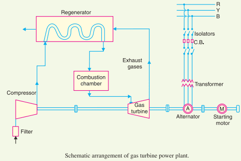 |
| Gas turbine power plant layout |
(iii) Combustion chamber: The air at high pressure from the compressor is led to the combustion chamber via the regenerator. In the combustion chamber, heat is added to the air by burning oil. The oil is injected through the burner into the chamber at high pressure to ensure atomisation of oil and its thorough mixing with air. The result is that the chamber attains a very high temperature (about 3000 F). The combustion gases are suitably cooled to 1300F to 1500F and then delivered to the gas turbine.
(iv) Gas turbine: The products of combustion consisting of a mixture of gases at high temperature and pressure are passed to the gas turbine.These gases in passing over the turbine blades expand and thus do the mechanical work. The temperature of the exhaust gases from the turbine is about 900F.
(v) Alternator: The gas turbine is coupled to the alternator as seen in the gas turbine plant layout. The alternator converts mechanical energy of the turbine into electrical energy. The output from the alternator is given to the bus-bars through the transformer, circuit breakers and isolators.
(vi) Starting motor: Before starting the turbine, the compressor has to be started. For this purpose, an electric motor is mounted on the same shaft as that of the turbine. The motor is energised by the batteries. Once the unit starts, a part of the mechanical power of the turbine drives the compressor and there is no need of motor now.
Gas turbine power plant Advantages:
The following are the advantages of gas turbine power plant:
(i) It is simple in design as compared to steam power station since no boilers and their auxiliaries are required.
(ii) It is much smaller in size as compared to the steam power station of the same capacity. This is expected since the gas turbine power plant does not require a boiler, feed water arrangement etc.
(iii) The initial and operating costs are much lower than that of the equivalent steam power station.
(iv) It requires comparatively less water as no condenser is used.
(v) The maintenance charges are quite small.
(vi) Gas turbines are much simpler in construction and operation than steam turbines.
(vii) It can be started quickly form cold conditions.
(viii) There are no standby losses. However, in a steam power station, these losses occur because the boiler is kept in operation even when the steam turbine is supplying no load.
Must Read:
Gas turbine power plant Disadvantages:
The following are the disadvantages of gas turbine power plant:
(i) There is a problem with starting the unit. It is because before starting the turbine, the compressor has to be operated for which power is required from some external source. However, once the unit starts, the external power is not needed as the turbine itself supplies the necessary power to the compressor.
(ii) Since a greater part of power developed by the turbine is used in driving the compressor, the net output is low.
(iii) The overall efficiency of such plants is low (about 20%) because the exhaust gases from the turbine contain sufficient heat.
(iv) The temperature of the combustion chamber is quite high (3000F) so that its life is comparatively reduced.
Oh my goodness! an amazing article dude. Thank you However I am experiencing issue with ur rss . Don’t know why Unable to subscribe to it. Is there anyone getting identical rss problem? Anyone who knows kindly respond. Thnkx.
Thank you for your kind words about the article and comments!