Liquid Crystal Display(LCD):
The liquid crystal display (LCD) has the distinct advantage of having a lower power requirement than the LED.It is typically in the order of microwatts for the display, as compared to the same order of milliwatts for LEDs.It does, however, require an external or internal light source and is limited to a temperature range of about 0° to 60°C.Lifetime is an area of concern because LCDs can chemically degrade.The types receiving the major interest today are the field-effect and dynamic scattering units.Each will be covered in some detail in this section.
A liquid crystal is a material (normally organic for LCDs) that will flow like a liquid but whose molecular structure has some properties normally associated with solids.For the light-scattering units, the greatest interest is in the nematic liquid crystal, having the crystal structure shown in Fig. 20.35. The individual molecules have a rod like an appearance as shown in the figure.
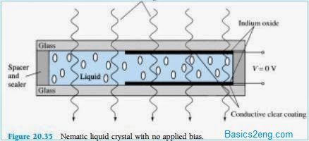
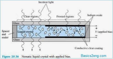
The indium oxide conducting surface is transparent, and under the condition shown in the figure, the incident light will simply pass through and the liquid-crystal structure will appear clear. If a voltage (for commercial units the threshold level is usually between 6 and 20 V) is applied across the conducting surfaces, as shown in Fig. 20.36, the molecular arrangement is disturbed, with the result that regions will be established with different indices of refraction.
The incident light is therefore reflected in different directions at the interface between regions of different indices of refraction (referred to as dynamic scattering – first studied by RCA in 1968) with the result that the scattered light has a frosted glass appearance. Note in Fig. 20.36, however, that the frosted look occurs only where the conducting surfaces are opposite each other and the remaining areas remain translucent.
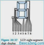
A digit on an LCD display may have the segment appearance shown in Fig. 20.37.The black area is actually a clear conducting surface connected to the terminals below for external control. Two similar masks are placed on opposite sides of a sealed thick layer of liquid-crystal material. If the number 2 were required, the terminals 8, 7, 3, 4, and 5 would be energized, and only those regions would be frosted while the other areas would remain clear.
As indicated earlier, the LCD does not generate its own light but depends on an external or internal source. Under dark conditions, it would be necessary for the unit to have its own internal light source either behind or to the side of the LCD. During the day, or in lighted areas, a reflector can be put behind the LCD to reflect the light back through the display for maximum intensity. For optimum operation, current watch manufacturers are using a combination of the transmissive (own light source) and reflective modes called transflective.
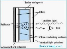
The field-effect or twisted nematic LCD has the same segment appearance and a thin layer of encapsulated liquid crystal, but its mode of operation is very different.Similar to the dynamic-scattering LCD, the field-effect LCD can be operated in the reflective or transmissive mode with an internal source. The transmissive display appears in Fig. 20.38. The internal light source is on the right, and the viewer is on the left.This figure is most noticeably different from Fig. 20.35 in that there is an addition of a light polarizer. Only the vertical component of the entering light on the right can pass through the vertical-light polarizer on the right.
 |
| Fig. 20.38 |
In the field-effect LCD, either the clear conducting surface to the right is chemically etched or an organic film is applied to orient the molecules in the liquid crystal in the vertical plane, parallel to the cell wall. Note the rods to the far right in the liquid crystal. The opposite conducting surface is also treated to ensure that the molecules are 90° out of phase in the direction shown (horizontal) but still parallel to the cell wall.
In between the two walls of the liquid crystal, there is a general drift from one polarization to the other, as shown in the figure. The left-hand light polarizer is also such that it permits the passage of only the vertically polarized incident light. If there is no applied voltage to the conducting surfaces, the vertically polarized light enters the liquid-crystal region and follows the 90° bending of the molecular structure.Its horizontal polarization at the left hand vertical light polarizer does not allow it to pass through, and the viewer sees a uniformly dark pattern across the entire display.
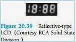
When a threshold voltage is applied(for commercial units from 2 to 8 V), the rodlike molecules align themselves with the field (perpendicular to the wall) and the light passes directly through without the 90° shift. The vertically incident light can then press directly through the second vertically polarized screen, and a light area is seen by the viewer. Through proper excitation of the segments of each digit, the pattern will appear as shown in Fig. 20.39.
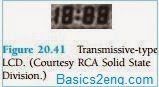
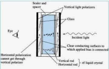
The reflective-type field-effect LCD is shown in Fig. 20.40. In this case, the horizontally polarized light at the far left encounters a horizontally polarized filter and passes through to the reflector, where it is reflected back into the liquid crystal, bent back to the other vertical polarization and returned to the observer.If there is no applied voltage, there is a uniformly lit display. The application of voltage results in a vertically incident light encountering a horizontally polarized filter at the left, which it will not be able to pass through and will be reflected. A dark area result on the crystal, and the pattern as shown in Fig. 20.41 appears.
 |
| Fig. 20.40 |
Field-effect LCDs are normally used when a source of energy is a prime factor (e.g., in watches, portable instrumentation, etc.) since they absorb considerably less power than the light-scattering types – the microwatt range compared to the low milliwatt range.The cost is typically higher for field-effect units, and their height is limited to about 2 in. while light-scattering units are available up to 8 in. in height.A further consideration in displays is turn-on and turn-off time.LCDs are characteristically much slower than LEDs.
LCDs typically have response times in the range 100 to 300 ms, while LEDs are available with response times below 100ns.However, there are numerous applications, such as in a watch, where the difference between 100 ns and 100 ms ( 1/10 of a second) is of little consequence.For such applications, the lower power demand of LCDs is a very attractive characteristic.The lifetime of LCD units is steadily increasing beyond the 10,000 hours limit.Since the colour generated by LCD units is dependent on the source of illumination, there is a greater range of colour choice.