Series fed Class-A Amplifier:
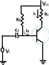
The simple fixed-bias circuit connection shown in the figure below can be used to discuss the main features of a series fed class A amplifier. The only differences between this circuit and the small-signal version considered previously are that the signals handled by the large-signal circuit are in the range of volts and the transistor used is a power transistor that is capable of operating in the range of a few to tens of watts.
As will be shown in this section, this circuit is not the best to use as a large-signal amplifier because of its poor power efficiency. The beta of a power transistor is generally less than 100, the overall amplifier circuit using power transistors that are capable of handling large power or current while not providing much voltage gain.
DC Bias Operation of series fed class A amplifier.:
The dc bias set by Vcc and RB fixes the dc base-bias current at
IB = (Vcc-0.7V)/RB
with the collector current then being
Ic =B(beta) IB
with the collector-emitter voltage then
VCE=Vcc -Ic Rc
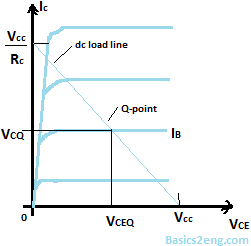
To appreciate the importance of the dc bias on the operation of the power amplifier, consider the collector characteristic shown in the figure. An AC load line is drawn using the values of Vcc and Rc. The intersection of the dc bias value of IB with the dc load line then determines the operating point (Q-point) for the circuit. The quiescent point values are those calculated using Eqs. (16.1) through (16.3).
This textbook “Principles of Electrical Engineering and Elecronics by V.K Mehta” is the best in industry. Grab it now for very less price.
If the dc bias collector current is set at one-half the possible signal swing (between 0 and Vcc/Rc), the largest collector current swing will be possible. Additionally, if the quiescent collector-emitter voltage is set at one-half the supply voltage, the largest voltage swing will be possible. With the Q-point set at this optimum bias point, the power considerations for the circuit of Fig. below are determined.
When an input ac signal is applied to the amplifier of Fig. 16.2, the output will vary from its dc bias operating voltage and current. A small input signal will cause the base current to vary above and below the dc bias point, which will then cause the collector current (output) to vary from the dc bias point set as well as the collector-emitter voltage to vary around its dc bias value.
As the input signal is made larger, the output will vary further around the established dc bias point until either the current or the voltage reaches a limiting condition. For the current, this limiting condition is either zero current at the low end or Vcc/Rc at the high end of its swing. For the collector-emitter voltage, the limit is either 0 V or the supply voltage, Vcc.
Power Considerations of series fed class A amplifier.:
The power into an amplifier is provided by the supply. With no input signal, the dc current drawn is the collector bias current, ICQ. The power then drawn from the supply is
Pi(dc) = VCC ICQ
Even with an AC signal applied, the average current drawn from the supply remains the same, so that the above equation represents the input power supplied to the series fed class A amplifier.
Output power of series fed class A amplifier.:
The output voltage and current varying around the bias point provide ac power to the load. This ac power is delivered to the load, RC, in the circuit of Fig. 16.2. The ac signal, Vi, causes the base current to vary around the dc bias current and the collector current around its quiescent level, ICQ.
The ac input signal results in ac current and ac voltage signals. The larger the input signal, the larger the output swing, up to the maximum set by the circuit. The ac power delivered to the load (RC) can be expressed in a number of ways.
Po(ac) = VCE IC
Po(ac) = (IC * IC )* RC
Maximum Efficiency of series fed class A amplifier.:
For the series fed class A amplifier., the maximum efficiency can be determined using the maximum voltage and current swings. For the voltage swing, it is
max VCE(p-p) = VCC
For the current swing, it is
max IC(p-p) = VCC/RC
max Po(ac) = [VCC(VCC/RC)]/8
The maximum power input can be calculated using the dc bias current set to one-half the maximum value:
max Pi(dc) = VCC (max IC) = VCC (VCC/RC)/2
we can calculate the max. efficiency as follows:
Max efficiency = Po(ac)/Pi(dc) = { [VCC(VCC/RC)]/8}/ [VCC (VCC/RC)/2]
= 25%
The maximum efficiency of a series fed class A amplifier is thus seen to be 25%. Since this maximum efficiency will occur only for ideal conditions of both voltage swing and current swing, most series fed circuits will provide efficiencies of much less than 25%.