Transformer coupled class-A amplifier:
Here we will be discussing Transformer coupled class-A amplifier.A form of class A amplifier having a maximum efficiency of 50% uses a transformer to couple the output signal to the load as shown in the below figure. This is a simple circuit form to use in presenting a few basic concepts.More practical circuit versions are covered later.Since the circuit uses a transformer to step voltage or current, a review of voltage and current step-up and step-down is presented next.

A transformer can increase or decrease voltage or current levels according to the turns ratio, as explained below. In addition, the impedance connected to one side of a transformer can be made to appear either larger or smaller (step up or step down) at the other side of the transformer, depending on the square of the transformer winding turns ratio.The following discussion assumes ideal (100%) power transfer from primary to secondary, that is, no power losses are considered.
Must Read:
Voltage Transformation:
The transformer can step up or step down a voltage applied to one side directly as the ratio of the turns (or a number of windings) on each side.The voltage transformation is given by
V2/V1 = N2/N1
The equation above shows that if the number of turns of wire on the secondary side is larger than on the primary, the voltage at the secondary side is larger than the voltage on the primary side.
Current Transformation:
The current in the secondary winding is inversely proportional to the number of turns in the windings. The current transformation is given by
I2/I1 = N2/N1
Operation of Transformer coupled class-A amplifier:
The transformer (dc) winding resistance determines the dc load line for the circuit of Fig. 16.6. Typically, this dc resistance is small (ideally 0 ohms ) and, as shown, a 0 ohm dc load line is a straight vertical line. A practical transformer winding resistance would be a few ohms, but only the ideal case will be considered in this discussion. There is no dc voltage drop across the 0 ohm dc load resistance, and the load line is drawn straight vertically from the voltage point, VCEQ = VCC.
Efficiency of Transformer coupled class-A amplifier:
So far we have considered calculating the AC power delivered to the load. We next consider the input power from the battery, power losses in the amplifier, and the overall power efficiency of the transformer coupled class A amplifier. The input (dc) power obtained from the supply is calculated from the supply dc voltage and the average power drawn from the supply:
Pi(dc) = VCC ICQ
For the transformer coupled class A amplifier, the power dissipated by the transformer is small (due to the small dc resistance of a coil) and will be ignored in the present calculations. Thus the only power loss considered here is that dissipated by the power transistor and calculating using
PQ = Pi(dc) – Po(ac)
where PQ is the power dissipated as heat.While the equation is simple, it is nevertheless significant when operating a class A amplifier.The amount of power dissipated by the transistor is the difference between that drawn from the dc supply (set by the bias point) and the amount delivered to the AC load. When the input signal is very small, with very little AC power delivered to the load, the maximum power is dissipated by the transistor. When the input signal is larger and power delivered to the load is larger, less power is dissipated by the transistor. In other words, the transistor of a class A amplifier has to work hardest (dissipate the most power) when the load is disconnected from the amplifier, and the transistor dissipates least power when the load is drawing maximum power from the circuit.
MAXIMUM THEORETICAL EFFICIENCY:
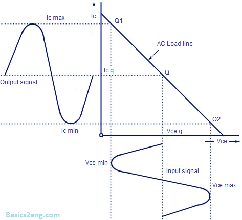
For a transformer coupled class A amplifier, the maximum theoretical efficiency goes up to 50%.Based on the signals obtained using the amplifier, the efficiency can be expressed as
efficiency (%) = 50 [(VCE(max)-VCE(min))/(VCE(max)+VCE(min))]^(2) %
The larger the value of VCE(max) and the smaller the value of VCE(min) ,the closer the efficiency approaches the theoretical limit of 50%.
Where you have in the section "Current Transformation:" The formula should read
I2/I1 = N1/N2