Commutation in DC Machine or Generator or Motor:
The figure below shows the schematic diagram of 2-pole lap-wound generator.Now you will know about commutation in dc machine or generator. There are two parallel paths between the brushes. Therefore, each coil of the winding carries one-half (Ia/2 in this case) of the total current (Ia) entering or leaving the armature.Note that the currents in the coils connected to a brush are either all towards the brush (positive brush) or all directed away from the brush (negative brush). Therefore, current in a coil will reverse as the coil passes a brush. This reversal of current as the coil passes & brush is called commutation.
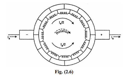
The reversal of current in a coil as the coil passes the brush axis is called commutation.When commutation takes place, the coil undergoing commutation is short-circuited by the brush. The brief period during which the coil remains short-circuited is known as commutation period Tc. If the current reversal is completed by the end of commutation period, it is called ideal commutation.If the current reversal is not completed by that time, then sparking occurs between the brush and the commutator which results in progressive damage to both.
Methods of Improving Commutation:
Improving commutation means to make the current reversal in the short-circuited coil as sparkless as possible. The following are the two principal methods of improving commutation:
(i) Resistance commutation
(ii) E.M.F. commutation
We shall discuss each method in turn.
(i) Resistance Commutation:
The reversal of current in a coil (i.e., commutation) takes place while the coil is short-circuited by the brush. Therefore, there are two parallel paths for the current as long as the short circuit exists. If the contact resistance between the brush and the commutator is made large, then current would divide in the
inverse ratio of contact resistances (as for any two resistances in parallel). This is the key point in improving commutation in dc machines.This is achieved by using carbon brushes (instead of Cu brushes) which have high contact resistance. This method of improving commutation is called resistance commutation.
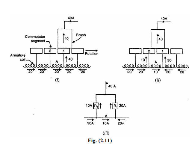
Figs. (2.11) and (2.12) illustrates how high contact resistance of carbon brush improves commutation (i.e., reversal of current) in coil A. In Fig. (2.11) (i), the brush is entirely on segment 1 and, therefore, the current in coil A is 20 A. The coil A is yet to undergo commutation. As the armature rotates, the brush short circuits the coil A and there are two parallel paths for the current into the brush.
(ii)Fig. (2.11) shows the instant when the brush is one-fourth on segment 2 and three-fourth on segment 1. The equivalent electric circuit is shown in Fig. (2.11).
(iii) where R1 and R2 represent the brush contact resistances on segments 1 and 2. A resistor is not shown for coil A since it is assumed that the coil resistance is negligible as compared to the brush contact resistance. The values of current in the parallel paths of the equivalent circuit are determined by the respective resistances of the paths. For the condition shown in Fig. (2.11) (ii), resistor R2 has three times the resistance of resistor R1. Therefore, the current distribution in the paths will be as shown. Note that current in coil A is reduced from 20 A to 10 A due to the division of current in (he inverse ratio of contact resistances. If the Cu brush is used (which has low contact resistance), R1 R2 and the current in coil A would not have reduced to 10 A.
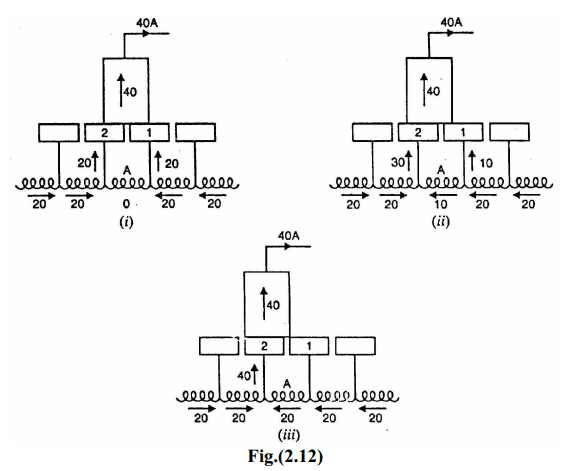
As the carbon brush passes over the commutator, the contact area with segment2 increases and that with segment 1 decreases i.e., R2 decreases and R1 increases.Therefore, more and more current passes to the brush through segment 2. This is illustrated in Figs. (2.12) (i) and (2.12) (ii), When the break between the brush and the segment 1 finally occurs [See Fig. 2.12 (iii)], the current in the coil is reversed and commutation is achieved.
It may be noted that the main cause of sparking during commutation is the production of reactance voltage and carbon brushes cannot prevent it.Nevertheless, the carbon brushes do help in improving commutation in dc machines.
The other minor advantages of carbon brushes are:
(i) The carbon lubricates and polishes the commutator.
(ii) If sparking occurs, it damages the commutator less than with copper
brushes and the damage to the brush itself is of little importance.
(ii)E.M.F. Commutation:
In this method, an arrangement is made to neutralise the reactance voltage by producing a reversing voltage in the coil undergoing commutation. The
reversing voltage acts in opposition to the reactance voltage and neutralizes it to some extent. If the reversing voltage is equal to the reactance voltage, the effect of the latter is completely wiped out and we get sparkless commutation.The reversing voltage may be produced in the following two ways:
(a) By brush shifting
(b) By using interpoles or compoles
(a) By brush shifting:
In this method, the brushes are given sufficient forward lead (for a generator) to bring the short-circuited coil (i.e., coil undergoing commutation in dc machines) under the influence of the next pole of opposite polarity.Since the short-circuited coil is now in the reversing field, the reversing voltage produced cancels the reactance voltage.This method suffers from the following drawbacks:
(a) The reactance voltage depends upon armature current. Therefore, the
brush shift will depend on the magnitude of armature current which
keeps on changing. This necessitates frequent shifting of brushes.
(b) The greater the armature current, the greater must be the forward lead for
a generator. This increases the demagnetizing effect of armature reaction
and further weakens the main field.
(b) By using interpoles or compoles:
The best method of neutralizing reactance voltage is by, using interpoles or
compoles.
Interpoles or Compoles:
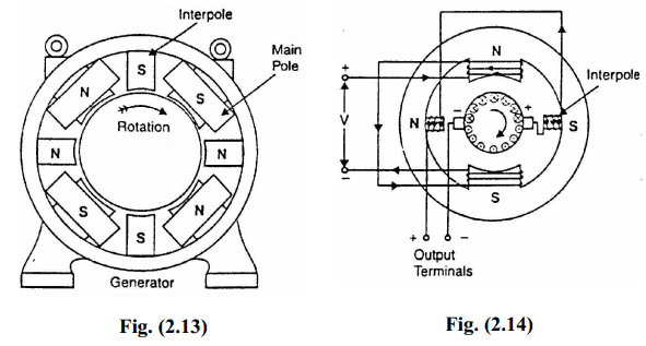
The best way to produce reversing voltage to neutralize the reactance voltage is by using interpoles or compoles. These are small poles fixed to the yoke and spaced mid-way between the main poles (See Fig. 2.13). They are wound with comparatively few turns and connected in series with the armature so that they carry armature current. Their polarity is the same as the next main pole ahead in the direction of rotation for a generator (See Fig. 2.13). Connections for a d.c. generator with interpoles is shown in Fig. (2.14).
Functions of Interpoles:
The machines fitted with interpoles have their brushes set on geometrical neutral axis (no lead).
The interpoles perform the following two functions:
(i) As their polarity is the same as the main pole ahead (for a generator), they
induce an e.m.f. in the coil (undergoing commutation) which opposes
reactance voltage. This leads to sparkless commutation. The e.m.f. induced
by compoles is known as commutating or reversing e.m.f. Since the
interpoles carry the armature current and the reactance voltage is also
proportional to armature current, the neutralization of reactance voltage is
automatic.
(ii) The m.m.f. of the compoles neutralizes the cross-magnetizing effect of
armature reaction in small region in the space between the main poles. It is
because the two m.m.f’s oppose each other in this region.
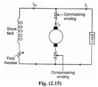
Fig. (2.15) shows the circuit diagram of a shunt generator with commutating winding and compensating winding. Both these windings are connected in series with the armature and so they carry the armature current.However, the functions they perform must be understood clearly.The main function of commutating winding is to produce reversing (or commutating) e.m.f. in order to cancel the reactance voltage. In addition to this, the m.m.f. of the commutating winding neutralizes the crossmagnetizing ampere-turns in the space between the main poles.The compensating winding neutralizes the cross-magnetizing effect of armature reaction under the pole faces.
Thank you.you give all details about communication .