Kelvin Double bridge for Low Resistance Measurement:
The Kelvin Bridge circuit is a modification of Wheatstone Bridge.An understanding of the kelvin Bridge arrangement may PV be obtained by a study of difficulties that arise in a Wheatstone bridge on account of the resistance of the leads and the contact resistances while measuring low valued resistors.
Consider the bridge circuit shown below where ‘r’ represents the resistance of the lead that connects the unknown resistance ‘R’ to standard resistance ‘S’.Two galvanometer connections indicated by dotted lines are possible. The connection may be either to point ‘m’ or to point ‘n’.When the galvanometer is connected to point ‘m’ , the resistance ‘r’,of the connecting leads is added to the standard resistance ‘S’ resulting in indication of too low an induction for unknown resistance R.When the connection is made to point ‘n’,the resistance ‘r’, is added to the unknown resistance resulting in indication of too high a value for R.
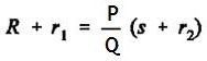
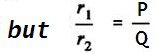
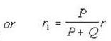
Suppose that instead of using point ‘m’ , which gives a low result or ‘n’,which makes the result high,we make the galvanometer connection to any intermediate point ‘d as shown by full line in below figure.If a point ‘d’ the resistance ‘r’ is divided into two parts r1 and r2, such that ,

Must Read:
- Measurement of Resistance | Ammeter-Voltmeter Method
- ElectrodynamometerInstruments Construction and Operation
- Permanent Magnet Moving Coil Instrument or PMMC Instrument
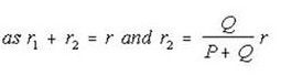
Then the presence of r1, the resistance of connecting leads, causes no error in the result. We have
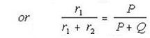
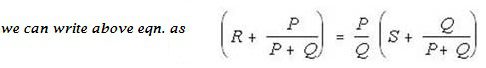
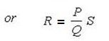
Therefore we conclude that making the galvanometer connection as at ‘c’, the resistance of leads does not affect the result.
The Kelvin double bridge method described above is obviously not a practical way of achieving the desired, result, as there would certainly be a trouble in determining the correct point for galvanometer connections.So the simple modification is that two actual resistance units of character ratio be connected between points m and n, the galvanometer be connected to the junction of the resistors.This is the actual kelvin bridge arrangement which is shown below.
The Kelvin double bridge incorporates the idea of a second set of ratio arms – hence the name double bridge has come and the use of four terminal resistors for low resistance arms. Below figure shows the schematic diagram of kelvin double bridge. The second set of ratio arms p and q is used to connect the galvanometer to a point d at the appropriate potential between points m and n to eliminate the effect of connecting lead of resistance r between the known resistance R and the standard resistance S.
 |
| Kelvin Double Bridge Method for Low Resistance Measurement |
The ratio p/q is made equal to P/Q . Under balanced conditions, there is no current through the galvanometer, which means that the voltage drop between a and b,Eab is equal to the voltage drop Eamd between a and c.
Now,
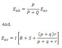
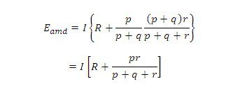
For zero galvanometer deflection,
Eab = Eamd
 eqn.1
eqn.1
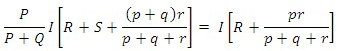
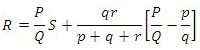
Now if P/Q = p/q , equation above becomes
![]() eqn.2
eqn.2
Equation 2 to is the usual working equation for Kelvin Bridge circuit. It indicates that the resistance of connecting lead ‘r’ has no effect on the measurement, provided that the two sets of ratio arms have equal ratios. Equation 1, however, as it shows the error that is introduced in case the ratios are not exactly Ω equal. It indicates that it is desirable to keep r as small as possible in order to minimise the errors in case there is a difference between ratios P/Q and p/q.
The effect of thermoelectric emf‘s can be eliminated by making another measurement with the battery connections reversed. The true value of R being the mean of the two readings.