Hello Mr./Mrs. visitor. First of all thanks for visiting electrical engineering info Now let us discuss potential distribution in a string of suspension insulators. Let us know how the potential is distributed over each unit of suspension insulator whether is it uniform or non-uniform.
Potential distribution over a string of suspension insulators:
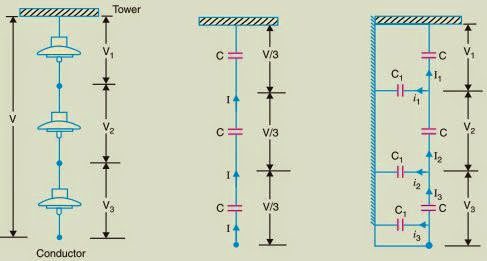
A string of suspension insulators consists of a number of porcelain discs connected in series through metallic links. Figure (i) shows 3-disc string of suspension insulators. The porcelain portion of each disc is between two metal links. Therefore, each disc forms a capacitor C as shown in Figure(ii).
This is known as mutual capacitance or self-capacitance. If there were mutual capacitance alone, then charging current would have been the same through all the discs and consequently, the voltage across each unit would have been the same i.e., V/3 as shown in Figure (ii). However, in actual practice, capacitance also exists between metal fitting of each disc and tower or earth. This is known as shunt capacitance C1.
Due to shunt capacitance, charging current is not the same through all the discs of the string. Therefore, the voltage across each disc will be different. Obviously, the disc nearest to the line conductor will have the maximum voltage. Thus referring to Figure (iii), V3 will be much more than V2 or V1.
The following points may be noted regarding the potential distribution over a string of suspension insulators :
(i) The voltage impressed on a string of suspension insulators does not distribute itself uniformly across the individual discs due to the presence of shunt capacitance.
(ii) The disc nearest to the conductor has maximum voltage across it. As we move towards the cross-arm, the voltage across each disc goes on decreasing.
(iii) The unit nearest to the conductor is under maximum electrical stress and is likely to be punctured. Therefore, means must be provided to equalise the potential across each unit.
(iv) If the voltage impressed across the string were d.c., then the voltage across each unit would be the same. It is because insulator capacitances are ineffective for DC.
This textbook “Principles of Power System by V.K Mehta” is the best in industry. Grab it now for very less price.
Mathematical expression: Figure below shows the equivalent circuit for a 3-disc string. Let us suppose that self-capacitance of each disc is C. Let us further assume that shunt capacitance C1 is some fraction K of self-capacitance i.e., C1 = KC. Starting from the cross-arm or tower, the voltage across each unit is V1, V2 and V3 respectively as shown.
Applying Kirchhoff’s current law to node A, we get,
I2= I1+ i1
or V2ωC = V1ω C + V1ω C1
or V2ω C = V1ω C + V1ωKC
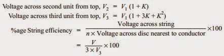
∴ V2= V1(1 + K) …(i)
Applying Kirchhoff’s current law to node B, we get,
I3= I2+ i2
or V3ω C = V2ω C + (V1+ V2) ω C1
or V3ω C = V2ω C + (V1+ V2) ω K C
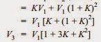
or V3= V2+ (V1+ V2)K
= KV1+ V2(1 + K)
The voltage between conductor and earth (i.e., tower) is
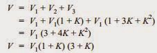
From expressions (i), (ii) and (iii), we get,
![]()
∴Voltage across the top unit,
![]()
The following points may be noted from the above mathematical analysis :
(i) If K = 0·2 (Say), then from exp. (iv), we get, V2= 1·2 V1 and V3= 1·64 V1. This clearly shows that disc nearest to the conductor has maximum voltage across it; the voltage across other discs decreasing progressively as the cross-arm in approached.
(ii) The greater the value of K (= C1/C), the more non-uniform is the potential across the discs and lesser is the string efficiency.
(iii) The inequality in voltage distribution increases with the increase of the number of discs in the string. Therefore, a shorter string has more efficiency than the larger one.