The ability of an SCR to control large currents in a load by means of small gate current makes this device useful in switching and control applications. Some of the important applications of SCR are discussed below :
(i)Application of SCR as static contactor: An important application of SCR is for switching operations. As SCR has no moving parts, therefore, when it is used as a switch, it is often called a static contactor.
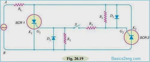
The above figure shows the use of SCR to switch ON or OFF a.c. power to a load RL.Resistances R1 and R2 are for the protection of diodes D1 and D2 respectively.Resistance R3 is the gate current limiting resistor.To start the circuit, switch is closed.During the positive half-cycle of a.c. supply, end A is positive and end B is negative.Then diode D2 sends gate current through SCR1.
Therefore SCR1 is turned ON while SCR2 remains OFF as its anode is negative w.r.t. cathode.The current conduction by SCR1 follows the path ARLK1BA. Similarly, in the next half-cycle, SCR2 is turned ON and conducts current through the load. It may be seen that switch S handles only a few mA of gate current to switch ON several hundred amperes in the load RL.This is a distinct advantage over a mechanical switch.
(ii)Application of SCR for power control: It is often necessary to control power delivered to some load such as the heating element of a furnace.Series resistances or potentiometers cannot be used because they waste power in high power circuits.Under such conditions, silicon controlled rectifiers are used which are capable of adjusting the transmitted power with little waste.The below figure shows a common circuit for controlling power in the load RL.During the positive half-cycle of a.c. supply, end A is positive and end B is negative.
Therefore, capacitor C2 is charged through AD1RC2D4B.The charge on the capacitor C2 depends upon the value of potentiometer R.When the capacitor C2 is charged through a sufficient voltage, it discharges through the zener Z.This gives a pulse to the primary and hence secondary of transformer T2.This turns on SCR2 which conducts currents through the load RL.During negative half-cycle of supply, the capacitor C1 is charged.It discharges through the zener and fires SCR1 which conducts current through the load.
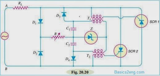
The angle of conduction can be controlled by the potentiometer R.The greater the resistance of R, lesser is the voltage across C1 or C2 and hence smaller will be the time during which SCR1 and SCR2 will conduct in a full cycle.In this way, we can control a large power of several kW in the load RL with the help of a small potentiometer R.
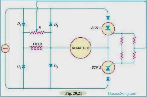
(iii)Application of SCRs for speed control of d.c. shunt motor: The conventional method of speed control of d.c. shunt motor is to change the field excitation.But change in field excitation changes the motor torque also.This drawback is overcome in SCR control as shown in the below figure. Diodes D1, D2, D3 and D4 form the bridge.This bridge circuit converts a.c. into d.c. and supplies it to the field winding of the motor.
During the positive half-cycle of a.c. supply, SCR1 conducts because it gets gate current from bridge circuit as well as its anode is positive w.r.t. cathode.The armature winding of the motor gets current.
The angle of conduction can be changed by varying the gate current. During the negative half-cycle of a.c. supply, SCR2 provides current to the armature winding.In this way, the voltage fed to the motor armature and hence the speed can be controlled.
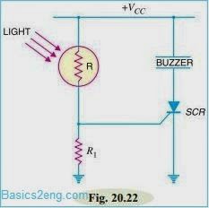
(iv)Application of SCR Overlight detector: The below figure shows the use of SCR for overlight detection.The resistor R is a photo-resistor, a device whose resistance decreases with the increase in light intensity.When the light falling on R has normal intensity, the value of R is high enough and the voltage across R1 is insufficient to trigger the SCR.
However, when R is in strong light, its resistance decreases and the voltage drop across R1 becomes high enough to trigger the SCR.Consequently, the buzzer sounds the alarm.It may be noted that even if the strong light disappears, the buzzer continues to sound the alarm. It is because once the SCR is fired, the gate loses all control.
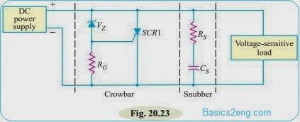
(v)Application of SCR Crowbar: A crowbar is a circuit that is used to protect a voltage-sensitive load from excessive d.c. power supply output voltages.The below figure shows the SCR crowbar circuit.It consists of a zener diode, a gate resistor RG and an SCR.It also contains a snubber to prevent false triggering.
Operation: The circuit action is as under:
(a)Under normal conditions, the zener diode and the SCR are OFF.With zener diode being in cutoff, there is no current through RG and no voltage drop occurs across this resistor.This means that the gate of SCR is at 0V so that the SCR is in the off state.Therefore, as long as zener diode is off, the SCR behaves as an open and will not affect either the d.c. power supply or the load.
(b)Suppose the output voltage from the dc power supply suddenly increases.This causes the zener diode to break down and conduct current.As the current flows through the zener diode, voltage is developed across resistor RG which causes the SCR to conduct current.When the SCR conducts, the voltage source is shorted by the SCR. The supply voltage fuse blows out and the load is protected from overvoltage.
Application of SCR in Normal Operation:
In order to operate the SCR in normal operation, the following points are kept in view :
(i) The supply voltage is generally much less than breakover voltage.
(ii) The SCR is turned on by passing an appropriate amount of gate current (a few mA) and not by breakover voltage.
(iii) When SCR is operated from a.c. supply, the peak reverse voltage which comes during negative half-cycle should not exceed the reverse breakdown voltage.
(iv) When SCR is to be turned OFF from the ON state, anode current should be reduced to holding current.
(v) If gate current is increased above the required value, the SCR will close at much reduced supply voltage.
Application of SCR as a Switch:
The SCR has only two states, namely; ON state and OFF state and no state in between. When appropriate gate current is passed, the SCR starts conducting heavily and remains in this position indefinitely even if gate voltage is removed.This corresponds to the ON condition.However, when the anode current is reduced to the holding current, the SCR is turned OFF.It is clear that behaviour of SCR is similar to a mechanical switch.As SCR is an electronic device, therefore, it is more appropriate to call it an electronic switch.
Advantages of SCR as a switch:
An SCR has the following advantages over a mechanical or electromechanical switch (relay) :
(i) It has no moving parts.Consequently, it gives noiseless operation at high efficiency.
(ii) The switching speed is very high up to 10^9 operations per second.
(iii) It permits control over large current (30–100 A) in the load by means of a small gate current (a few mA).
(iv) It has small size and gives trouble free service.
SCR Switching:
We have seen that SCR behaves as a switch i.e. it has only two states viz. ON state and OFF state.It is profitable to discuss the methods employed to turn-on or turn-off an SCR.
1. SCR turn-on methods: In order to turn on the SCR, the gate voltage VG is increased up to a minimum value to initiate triggering.This minimum value of gate voltage at which SCR is turned ON is called gate triggering voltage VGT.The resulting gate current is called gate triggering current IGT.Thus to turn on an SCR all that we have to do is to apply positive gate voltage equal to VGT or pass a gate current equal to IGT.For most of the SCRs, VGT = 2 to 10 V and IGT = 100 µA to 1500 mA.We shall discuss two methods to turn on an SCR.
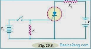
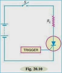
(i) D.C. gate trigger circuit: The below figure shows a typical circuit used for triggering an SCR with a d.c. gate bias. When the switch is closed, the gate receives sufficient positive voltage (= VGT) to turn the SCR on. The resistance R1 connected in the circuit provides noise suppression and improves the turn-on time.The turn-on time primarily depends upon the magnitude of the gate current.The higher the gate-triggered current, the shorter the turn-on time.
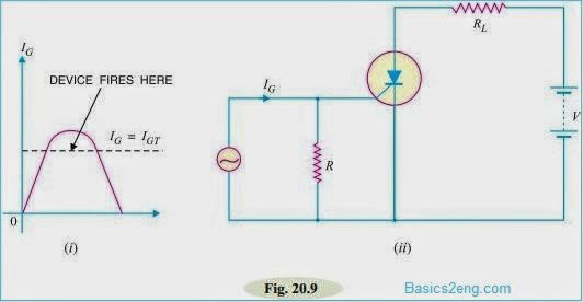
(ii) A.C. trigger circuit: An SCR can also be turned on with positive cycle of a.c. gate current.The figure(ii) below shows such a circuit.During the positive half-cycle of the gate current, at some point IG = IGT , the device is turned on as shown in the figure (i) below.
2. SCR turn-off methods: The SCR turn-off poses more problems than SCR turn-on.It is because once the device is ON, the gate loses all control.There are many methods of SCR turn-off but only two will be discussed.
(i) Anode current interruption: When the anode current is reduced below a minimum value called holding current, the SCR turns off.The simple way to turn off the SCR is to open the line switch S as shown in the below figure.
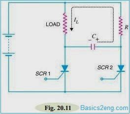
(ii) Forced commutation: The method of discharging a capacitor in parallel with an SCR to turn off the SCR is called forced commutation.The below figure shows the forced commutation of SCR where capacitor C performs the commutation.Assuming the SCRs are switches with SCR1 ON and SCR2 OFF, current flows through the load and C as shown in the below figure.When SCR2 is triggered on, C is effectively paralleled across SCR1.The charge on C is then opposite to SCR1’s forward voltage, SCR1 is thus turned off and the current is transferred to R–SCR2 path.