Carey Foster Slide Wire Bridge:
Carey Foster Slide Wire Bridges is a device used to measure the resistance of an unknown circuit. It works on the principles of Ohm’s Law and is used as a troubleshooting resource for engineers.
As Carey Foster Slide Wire Bridge operates by applying analogue voltage, it is relatively inaccurate for modern measurements with digital devices such as multimeters. However, for measuring resistance in circuits with a range of 20kΩ to 1MΩ, Carey Foster Slide Wire Bridge is a more accurate tool than most multimeters.
Carey Foster Slide Wire Bridges has two metal plates with a wire running between them. By applying a voltage to the top plate and measuring the current flowing through the wire, the resistance of the circuit is determined. Carey Foster Slide Wire Bridges can measure varying resistances due to its adjustable top plate and the relative precision of Carey Foster Slide Wire Bridge measurements gives it greater accuracy than multimeters.
Carey Foster Slide Wire Bridge was invented by Carey W. Foster in 1934, who used his invention as a troubleshooting resource for engineers. Carey Foster Slide Wire Bridge is now manufactured by many companies, including Cole-Parmer and Hewlett Packard as a portable Carey Foster Slide Wire Bridge or as an accessory Carey Foster Slide Wire Bridge to be added onto other Carey Foster Slide Wire Bridges.
Benefits of Carey Foster Slide Wire Bridge:
– Carey Foster Slide Wire Bridges is a more accurate tool than most multimeters for measuring resistance in circuits with a range of 20kΩ to 1MΩ.
– Carey Foster Slide Wire Bridge has an adjustable top plate which gives it greater accuracy.
– Carey Foster Slide Wire Bridge is a portable Carey Foster Slide Wire Bridge and can be added onto Carey Foster Slide Wire Bridges as an accessory Carey Foster Slide Wire Bridge.
Disadvantages of Carey Foster Slide Wire Bridge:
– Carey Foster Slide Wire Bridges is relatively inaccurate for modern measurements and is not practical for use in lower circuits due to Carey Foster Slide Wire Bridges’ design.
– Carey Foster Slide Wire Bridge was designed to solve problems in the 1930s, and Carey Foster Slide Wire Bridge’s design does not allow Carey Foster Slide Wire
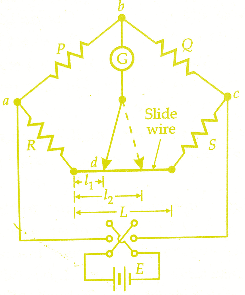
The connections of Carey Foster Slide Wire bridge are shown in the below figure. A slide-wire of length L being included between R and S as shown. Carey Foster Bridge is specially suited for the comparison of two nearly equal resistances.
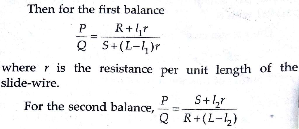
Resistances P and Q are first adjusted so that the ratio P / Q is approximately equal to the ratio R/S. Exact balance is obtained by adjustment of the sliding contact on the slide-wire.
 |
| Carey Foster Slide Wire Bridge |
Let l1 be the distance of the sliding contact form the left-hand end of the slide wire. The resistances R and S are then interchanged and balance again obtained. Let the distance now be l2.
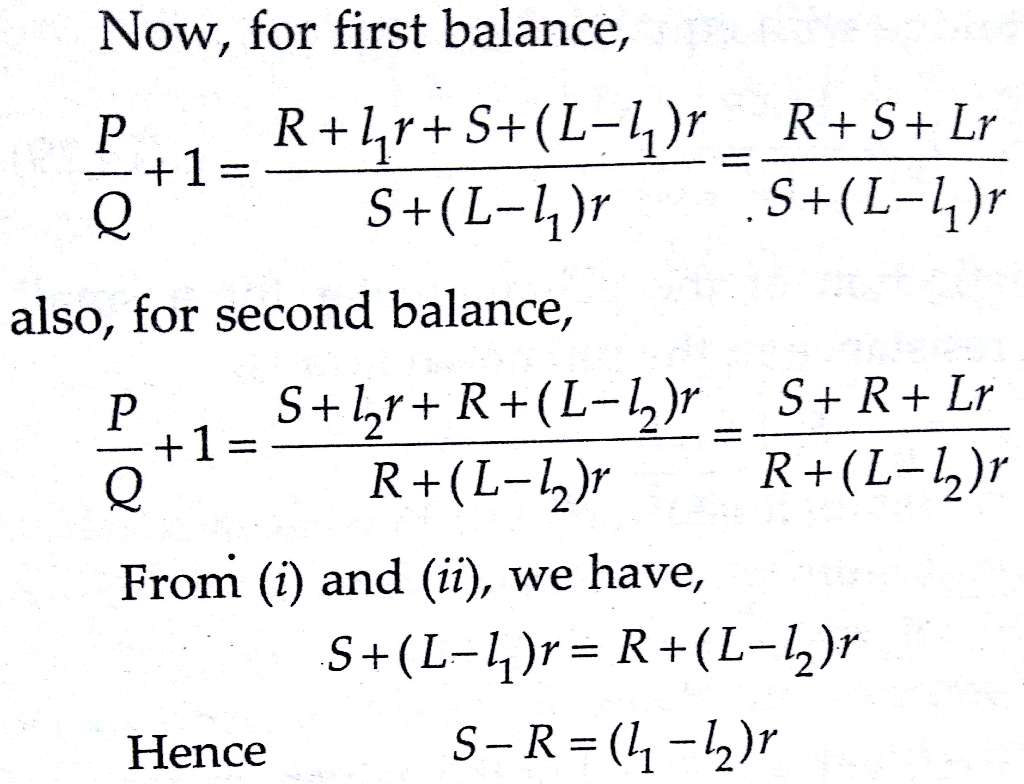
Thus the difference between S and R is obtained from the resistance per unit length of the slide wire together with the difference (l1–l2) between the two slide-wire lengths at balance.
The slide-wire is calibrated i.e., r is obtained by shunting either S or R by a known resistance and again determining the difference in length (l’1–l’2). Suppose that S is known and that S’ is its value when shunted by a known resistance; then
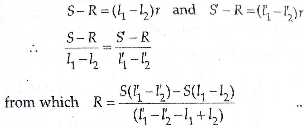
The equation above shows that Carey Foster Bridge method gives a direct comparison between S and R in terms of lengths only, the resistances of P and Q contact resistances, and the resistance of connecting leads being eliminated.
As it is important that the two resistors R and S shall not be handled or disturbed during the measurement, a special switch is used to affect the interchanging of these two resistors during the test.
Kelvin Varley Slide Divider :
A Kelvin Varley divider is used for voltage division. This method is very precise and finds extensive applications. A Kelvin Varley divider is shown in the below figure. It consists of several decades of resistors which are interconnected. The voltage division is carried out successively.
Each voltage division decade is made up of eleven equal resistors with successive division decades having a total resistance equal to twice the value of a unit resistor in the previous decade.
For example, in the Kelvin Varley divider shown in the below figure, there are four-decade dividers. This decade is constructed using 11 resistance coils having a resistance of 10 kΩ each.
The second-decade divider has 11 resistors of 2 kΩ) each. Similarly, the 3rd decade has 11 resistors of 400Ω each and the fourth and final decade has 10 resistors of 80Ω each.

The use of 11 resistors to obtain a decade voltage division enables the Kelvin Varley Slide to have a constant input resistance irrespective of which switch positions are connected on the various decades. However, this is strictly true if output terminals are open circuited. For example, decade 3 has a constant input resistance of :
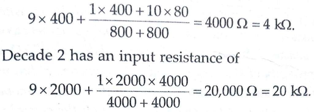
The input terminal impedance is 100kΩ irrespective of the switch position if it is assumed that the output current is negligible. The advantage of using the Kelvin Varley divider is the reduction of errors which arise on account of switch contact resistance due to current sharing within the device.
The disadvantages of the Kelvin Varley Slide are its calibration and the errors on account of temperature. The errors on account of temperature are due to the fact that the resistors carry different accounts and the changes in the value of r ohm resistance is different on account of different self-heating conditions.
The temperature effects can be reduced to negligible proportions by using resistors made of materials having a low resistance temperature coefficient. The error may be reduced to as low a value as ± 0.1 ppm. The principle of Kelvin-Varley Slides is used with advantage in potentiometers and universal shunts.
The figure below shows the use of Kelvin Varley divider in a Wheatstone bridge. The device is used to replace the simple slide wire with the advantage that it gives greater accuracy. For the case shown in the figure.
Conclusion:
Now here we have learnt Carey Foster Bridge & Kelvin Varley Divider. You can download this article as pdf, ppt.
Comment below for any Queries.