Errors in Current Transformers:
It is known that the value of transformation ratio (actual ratio) is not equal to the turns ratio in current transformers.Also, the value is not constant but depends upon the magnetizing and loss components of the exciting current, the secondary winding load current and its power factor.This means that the secondary winding current is not a constant fraction of the primary winding current but depends upon the factors listed above.This introduces considerable errors in current transformers.
In power measurements, it is necessary that the phase of secondary winding current shall be displaced by exactly 180° from that of the primary winding current. It is seen that the phase difference is different from 180° by an angle θ.
Thus in power measurements, owing to the use of CT two types of errors are introduced; one due to actual transformation ratio being different from the turns ratio and the other due to secondary winding current not being 180° out of phase with the primary winding current.
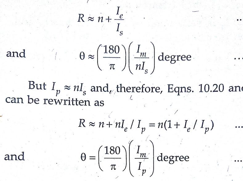
Approximate formulae for errors:
The usual instrument burden is largely resistive with some inductance and, therefore, δ is positive and is generally small.
Hence sin δ ≈ 0 and cos δ ≈1. Therefore, we can write transformation ratio as follows:
Characteristics of Current Transformers:
1.Effect of PF of secondary winding burden on errors—ratio error:
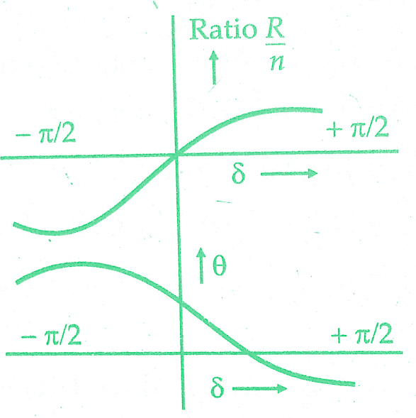
It is observed that for all inductive burdens the secondary winding current, ls lags behind the secondary induced voltage, Es so that δ is positive. Under these conditions, the actual transformation ratio is always greater than the turns ratio.For burdens which are sufficiently capacitive Is leads Es and so δ is negative.Under these conditions, the actual transformation ratio decreases becoming less than the turns ratio for values of δ approaching — 90°.
Phase angle: We find that for inductive burdens, phase angle δ is positive for small values of δ (high secondary p.f.) but becomes negative as the secondary burden becomes more inductive and δ approaches 90°. For negative values of δ (sufficiently capacitive burdens) δ is always positive. The variation of transformation ratio R and phase angle θ with δ is shown in the below figure. These conclusions are based on the assumption that the magnitude of secondary impedance remains constant.
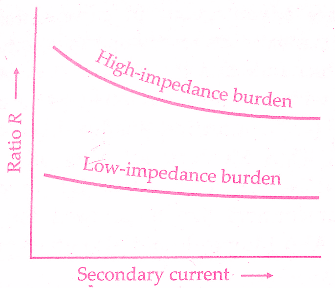
2. Effect of change of primary winding current:
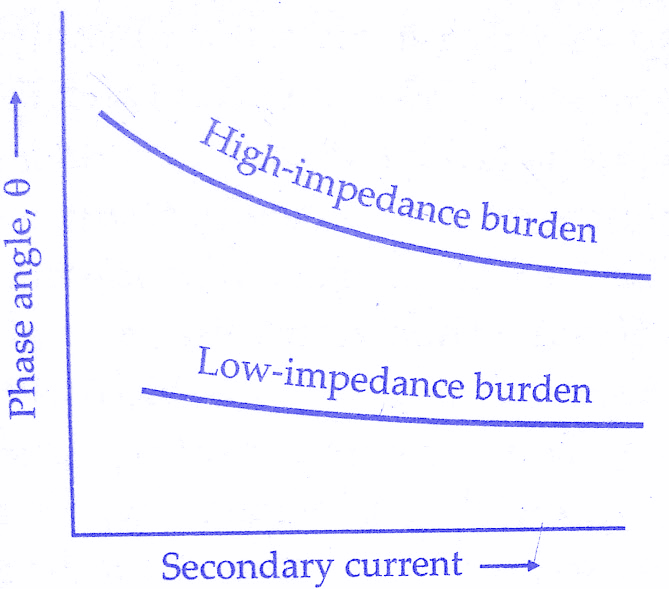
If the primary winding current changes the secondary winding current changes proportionately. At low values of current Ip (or. Is) current Im and loss component Ie are a greater proportion of Ip and, therefore, the errors are greater. As the current Ip increases, there is an increase in Is and there is a. decrease in ratio error and phase angle.The variation of ratio error and phase angle with secondary winding current is shown in below figures.
3.Effect of change in secondary’winding circuit burden:
An increase in secondary winding circuit burden impedance means an increase in volt ampere rating.This necessitates an increase in the secondary winding induced voltage which can be generated by an increased flux and flux density.Therefore both magnetizing-component Im and loss component Ie are increased.
Thus it is expected that errors will increase with the increase in secondary winding burden.In general, a greater burden impedance not only increases the transformation ratio but also shifts the phase angle between primary winding current and secondary winding current reversed to more positive values as shown in below figure.
4. Effect of change of frequency:
The effect of increase in frequency will result in proportionate decrease in flux density. Thus, in general, the effect of increase in frequency is similar to that produced by decrease in impedance of secondary winding burden.A current transformer is seldom used at a frequency which is very different from the one or which it is designed and, therefore, consideration of this effect is not very important.
Causes of Errors in Current Transformers:
In an ideal transformer, the actual transformation ratio would be equal to the turns ratio and the phase angle would be zero.However, as a result of physical limitations inherent in electric and magnetic circuits of the transformer, there are departures from this ideal and consequently, there are errors caused. The reasons are :
(i) There is some exciting mmf required by the primary winding to produce flux and,-therefore, the transformer draws a magnetizing current Im.
(ii) The transformer input must have a component which supplies the core losses (eddy current and hysteresis losses) and I²R losses of transformer windings due to flow of current I0.Therefore, loss component Ie is required to feed the losses associated with the flux and also the associated copper loss in winding due to the flow of I0.
(iii) The flux density in the core is not a linear function of the magnetizing force, i.e., the transformer core becomes saturated.
(iv) There is always a magnetic leakage and consequently, the primary flux linkages are not equal to the secondary flux linkages.
Methods to Reduce Errors in Current Transformers :
The difference between actual transformation ratio and the turns ratio depends largely on the loss component Ie and the transformer phase angle depends largely on magnetizing current It is obvious that if the ratio has to be close to the turns ratio and the phase angle is to be small, Ie and Im must be small as compared to Ip .There are some design features which help us to reduce errors in current transformers and they are discussed below :
Design Features of Current Transformers:
1)Core :
In order to minimize the errors the magnetizing current I„, and loss component I, must be kept to a low value. This means that the core must have a low reluctance and a low core loss.The reduction of the reluctance of flux path can be brought about by using materials of high permeability, short magnetic paths, large cross-section of core and a low value of flux density. The current transformers are, in fact, designed for much lower flux densities than that are used for power transformers.
This is especially important for current transformers used for protective relays which are frequently required to have a fair accuracy at currents many times the rated current (20 to 30 times the rated value), in order that the relay operation may be correct in the event of a short circuit or a fault on the system, particularly when differential relaying schemes are used.
The number of joints in building up cores should be minimum a far as possible because joints produce air gaps which offer paths of high reluctance for the flux.The mmf consumed by joints can be reduced by properly lapping the joints and tightly binding the core. The core loss is reduced by choosing materials having low hysteresis and low eddy current losses, and by working the core at low flux densities.
Present-day magnetic materials used in current transformers are divided into three categories :
(i) Hot rolled silicon steel ;
(ii) Cold rolled grain oriented silicon steel; and
(iii) Nickel iron alloys.
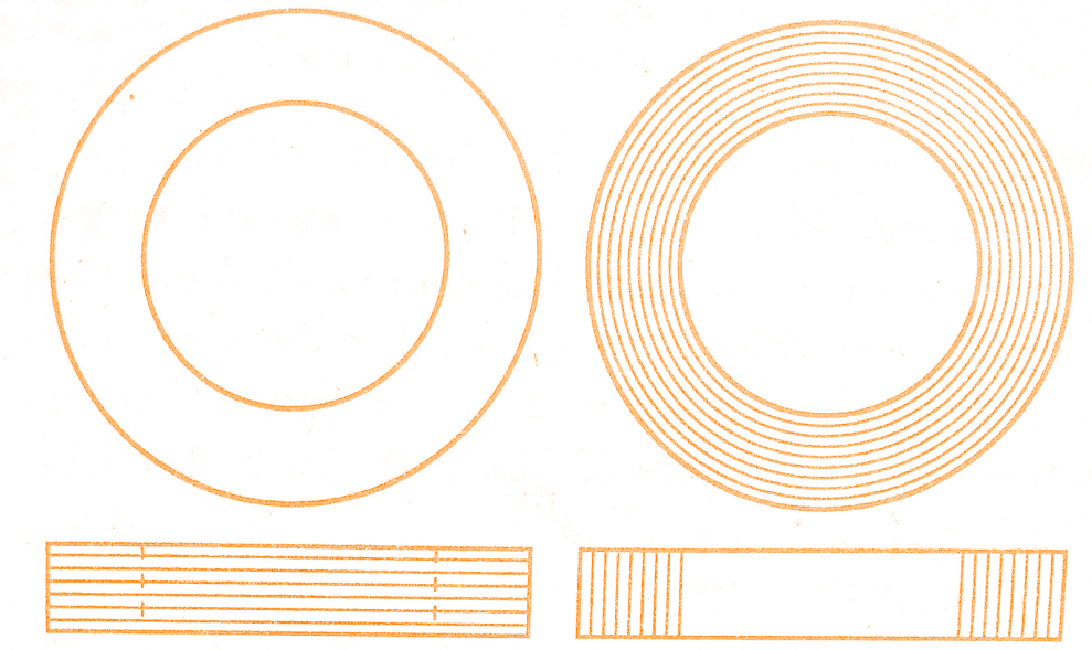
In current transformer practice, hot rolled silicon steels (4% silicon) are used in a variety of forms.For ring type, current transformers “ring” stampings are commonly used.For wound type, T-u,L or E and I stampings are used. In the highest grades of transformers, the core is built of ring shaped stampings stacked M cylindrical form as shown in the figure below.
An alternative method employs cores that are made of strip wound in spiral form like a clock spring.These are called toroidal cores.The latter method is much to be preferred when grain oriented magnetic materials are being used as it ensures that the flux path is always along the grains and hence there is minimum reluctance.Another advantage of the spiral type of cores is that the joints are entirely eliminated.
High permeability nickel iron cores are used for high precision current transformers.Mumetal (76% Ni) cores are very common as it has the property of high permeability, low loss and small retentivity all of which are advantageous in current transformer work.
But its maximum relative permeability (90,000) occurs with a flux density of only 0.35 Wb/m² as compared with the maximum relative permeability of silicon steel (4500) occurring at a flux density of about 0.5 Wb/m².Thus Mumetal saturates at a low flux density and is, therefore, not useful for protective current transformers like those used for overload relays etc.
Also, Mumetal (and also other nickel iron alloys) are costlier. Permendur (49% Co and 49% Fe) has the advantage of a very high saturation density of 2 to 4 Wb/m² as compared with 0.7 to 0.8 Wb/m² of other high permeability alloys. Hipernik (50% Fe and 50% Ni) has a high permeability at low flux densities and reasonable high saturation density and therefore it is frequently used for current transformers.
2)Primary winding current ratings:
Whatever equipment a current transformer is feeding, it is desirable that the ratio of exciting current to primary current should be small.This means that the ratio of excitation mmf to primary winding mmf should be low.It is difficult to achieve this condition if the latter quantity (primary winding current or mmf) is small and an improvement in performance is always obtained by increasing the primary winding mmf.Satisfactory results can usually be achieved if the total primary winding mmf at rated current is 5W A.
Thus transformers with a rated current of 500 A or more are provided with a single turn primary. Transformers for ratings below 500 A are where possible, provided with multiturn windings, if this enables the core size to be reduced.With the advent of improved magnetic materials and the development of methods for biasing the core to improve permeability, single turn primary winding can be used for even 100 A primary winding current.
3)Leakage reactance:
Leakage reactance tends to increase ratio error. Therefore, the two windings, primary and secondary should be close together to reduce the secondary winding leakage reactance.Use of ring shaped cores around which toroidal windings are uniformly distributed also leads to low values of 11, leakage reactance.
4)Turns compensation:
We have, actual, transformation ratio :
R = n + Ie/Is
Thus if we make the “nominal ratio” equal to the turns ratio the actual transformation ratio becomes more than the nominal ratio. Now if we reduce the turns ratio and keep the nominal ratio equal to the earlier value, the actual transformation ratio will be reduced.This would make actual transformation ratio nearly equal to the nominal ratio.Let us make it clear with the help of an example.
Let us consider a 1000/5 A current transformer with loss component equal to 0.6 percent of primary winding current.
Its nominal ratio, Kn = 1000/5 = 200
Loss component, I = (0.6/100) x 1000 = 6 A.
Let the number of primary turns, Np =1.
If the turns ratio is equal to the nominal ratio, we have n = 200.
Secondary winding turns,
NS = nNp =200×1=200
Actual ratio,
R = n+ Ie / IS = 200 + 6/5 = 201.2.
Now suppose we do not use 200 turns for the secondary winding and instead use 199 turns.
Actual transformation ratio with turns compensation
R = n + / = 199 + 6/5 = 200/2.
Thus we find that by reducing the secondary winding turns slightly, the actual transformation ratio is made nearly equal to the nominal ratio.
Usually, the best number of secondary winding turns is one or two less than the number which would make actual transformation ratio equal to the nominal ratio of the transformer. The phase angle error is effected very little by a change of one or two turns in the secondary winding. The correction by the reduction in secondary winding turns is exact only for a particular value of current and burden impedance.The current transformer, in this case, may be called “compensated”.
The errors can also be reduced by :
5)Use of shunts:
If the secondary winding current is too large, it may be reduced by a shunt placed across the primary or the secondary winding. This method makes an exact correction only for a particular value and type of burden. It also reduces phase angle error.
6)Wilson compensation method:
Reduction of one or two turns of the secondary winding, no doubt, reduces the ratio error, but it has no effect on the phase angle error. Also, this method is too coarse a method for ratio adjustment and therefore we must use a method which exercises a finer control, say which is equivalent to reduction to a fraction of a turn. A compensated type of design was given by S. Wilson of the General Electric Company.This method gives finer adjustments.
It employs a few turns of wire called auxiliary secondary turns passed through a hole in the core and connected in series with the secondary winding. A short-circuited turn is placed around one position of the core to improve the phase relationships.
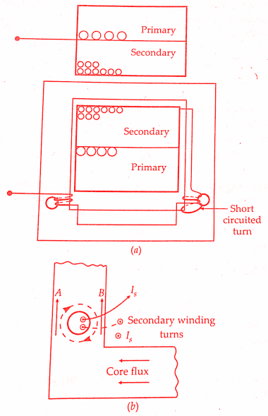
The auxiliary turns are connected to magnetize in the same direction around the core as the main secondary winding and thus their effect opposes the flux set up by the primary winding.The auxiliary turns tend to set up a circulating flux around the hole as indicated by the dotted line in above figure(b).The two fluxes are additive in section A of the core and subtractive in section B. At low flux densities the addition in flux is equal to the subtraction in flux.
However, as the flux densities increase (with larger currents and Is) section A tends to saturate so that the flux in section A is no longer linearly proportional to the current and the increase in flux in this portion is less than linear proportional to the current.
The action is equivalent to transforming some of the core flux to section B of the core, where it links with the auxiliary turns, and gives the effect of increased secondary winding turns.An increase of secondary turns means a reduction of I, as compared with an uncompensated transformer causing an increase in ratio R.
This action is needed to flatten the curves relating the ratio and phase angle with secondary current are flattened out so that the errors are practically constant (and of course known over a wide range of secondary winding current). This is the greatest advantage of this method.The curves can be lowered or raised by adjusting the number of auxiliary turns.
The shorted turns around part of the core make the flux in that part lag in phase behind the main flux.The action of this turn is like that of a shading band. The small lag effect produced on secondary winding current IS brings it closer to primary current Ip and thus phase angle errors are reduced.
7)Two stage design:
This design utilizes a second current transformer to correct the error in secondary current of first transformer.This method, in general, is applicable to an energy meter because a second coil is needed in the meter to carry the error-correcting current unless an auxiliary transformer is used.
Conclusion:
We have learnt errors & characteristics in Current Transformers and methods to reduce errors in Current Transformers.You can download this article as pdf, ppt.
Comment below for any Queries.